What is TTH test type?
TTH is considered to be an advanced form of shock vibration test type, which captures a complete temporal profile of the shock input, and records the precise amplitude and timing of the shock waveform at each moment during the test. The software forms a shock accelerogram by multiplying the base signal (sine, trapeze, etc.) by an envelope. As the base signal is always formed in the range from -1 to 1, after multiplication the acceleration by module will not exceed the envelope. The envelope together with the base signal provides smooth rise of the signal at the start of the accelerogram and smooth signal fall at its end. It helps eliminate sharp leaps of signal on the vibration shaker. The rate of signal rising and falling during the envelope edge and the duration of its fronts is specified by the user.
In simple terms, TTH can be characterized as a high-amplitude shock that gradually dampens out over time, much like a ball dropped from a table, where each subsequent impact is lower than the previous one.
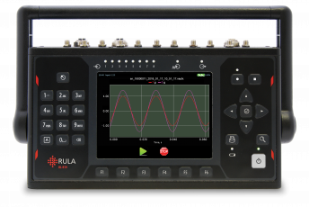
TTH test is typically recorded using high speed data acquisition systems, such as RL-C21, RL-C21M and RL-C25, and sensors, such as accelerometers or strain gauges which capture the instant response of the structure or device to the shock input. TTH vibration test is usually used when we cannot cover the shock requirements with regular shock or SRS test.
TTH enables running tests with shock pulses of different shapes:
- Sine shock;
- Cosine shock;
- Damped Sine wave;
- Teardrop;
- Sine chirp;
- Sawtooth chirp;
- Sine;
- Saw;
- Square wave;
- Random signal;
- Enveloped random signal;
- Enveloped random signal with PSD;
- Import from file.
What are the application spheres of TTH?
Transient time history (TTH) allows the user to simulate real-world shock transients on the object. TTH testing evaluates how components respond to transient loads like shocks and impacts, making it more suitable for assessing scenarios where dynamic behavior and sudden changes are crucial, like in crash testing or launch conditions.
TTH is applied in various fields:
- Aerospace: to assess the durability of components subjected to shock loads during events like takeoff and landing;
- Automotive: to evaluate vehicle components' performance during crash tests and road conditions;
- Electronics: to test the resilience of devices against drops and impacts, ensuring they can withstand everyday handling;
- Structural engineering: to analyze how structures respond to transient load events, such as earthquakes or explosive impacts.
What are the benefits of TTH?
TTH test type offers a number of benefits, including:
1. Comprehensive Time-Domain Analysis: TTH testing captures the entire load history over time, providing detailed insights into material behavior at specific moments;
2. Detailed Stress-Strain Responses: Allows for the evaluation of stress and strain responses at various points in time, helping to understand material limits under continuous loading;
3. Non-linear Behavior Examination: TTH can effectively assess non-linear material behaviors that occur over the span of transient events;
4. Multi-Dimensional Loading: It can accommodate complex loading patterns and interactions in multiple directions, which may not be fully represented in SRS testing;
5. Integration of Real Environmental Conditions: TTH can incorporate real-time environmental factors (like temperature changes) affecting material behavior during the transient period.
How to conduct TTH vibration test in TestUp?
To conduct TTH vibration test in RULA software TestUp, engineers need to define the appropriate test profile based on relevant standards or specific DUT requirements. These profiles are defined to replicate the specific shock events that a product may experience in its intended application. The key parameters of the TTH test profile include wavelet form and its synthesis parameters.
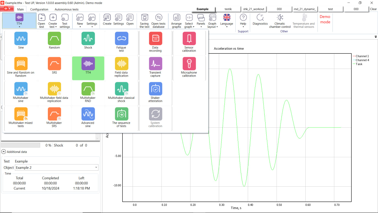
In TestUp software, TTH vibration test is set up and run in a few simple steps, as you can see in the screenshots below.
- Select TTH test.
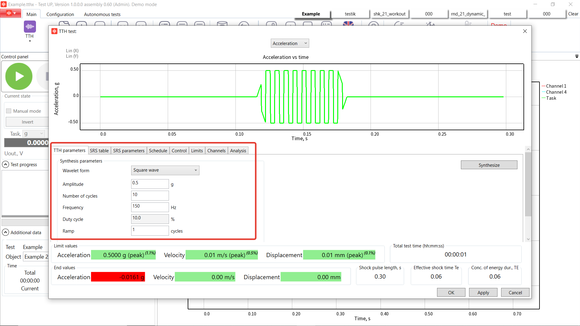
2. Create a new test profile. Today we’re going to make a ''Square wave'' shock with amplitude of half g, 10 cycles, and 150 Hz frequency. The ''Square wave'' wavelet form is characterized as a wave which consists of fixed frequency square pulses multiplied by trapezoidal edge smoothing function.
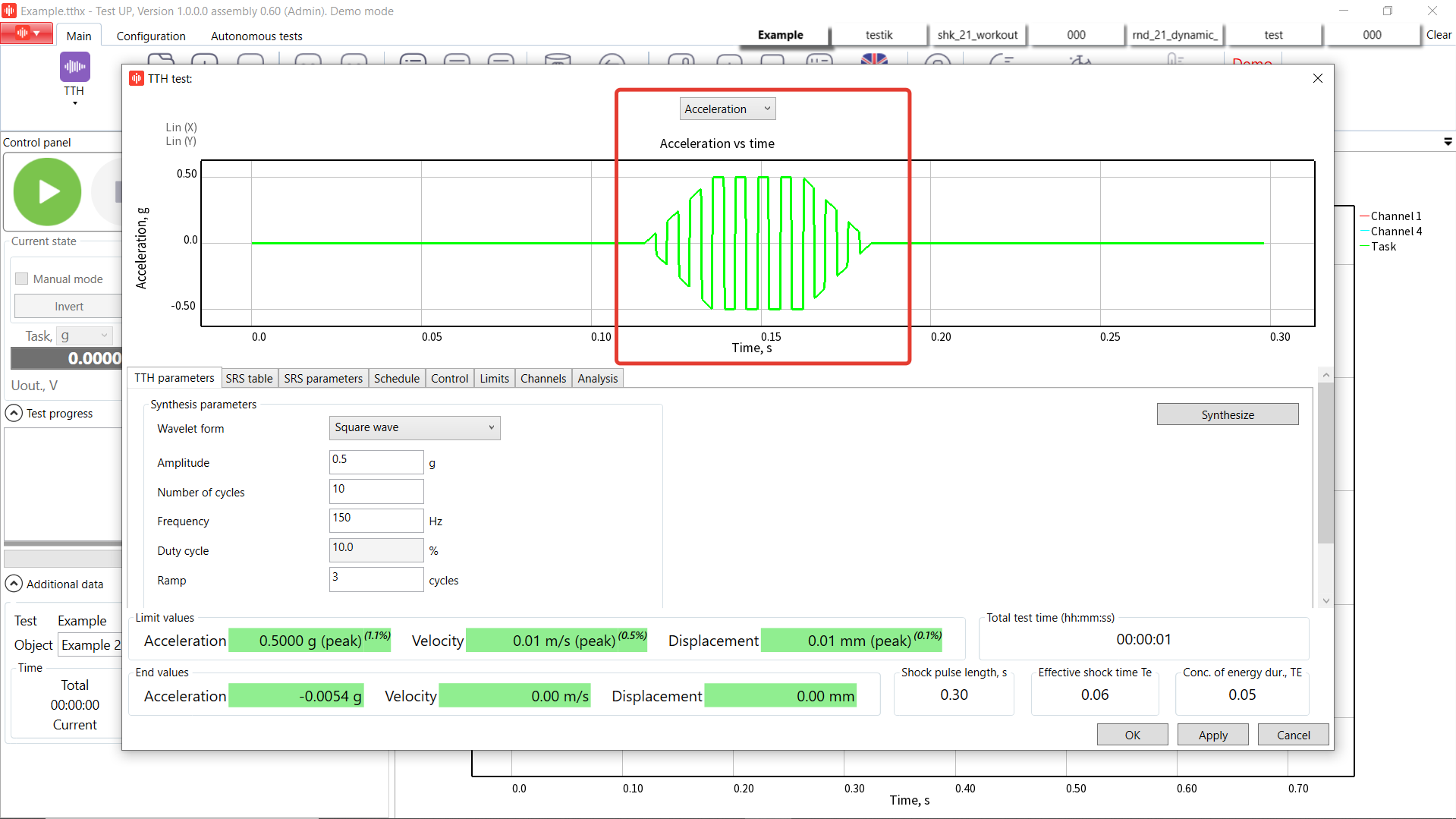
3. By changing the ramp cycles value we can change the number of cycles for the signal rising and lowering the level. Let’s set it as 3. After that, we press ''Synthesize'' button and now we can see the shock wave.
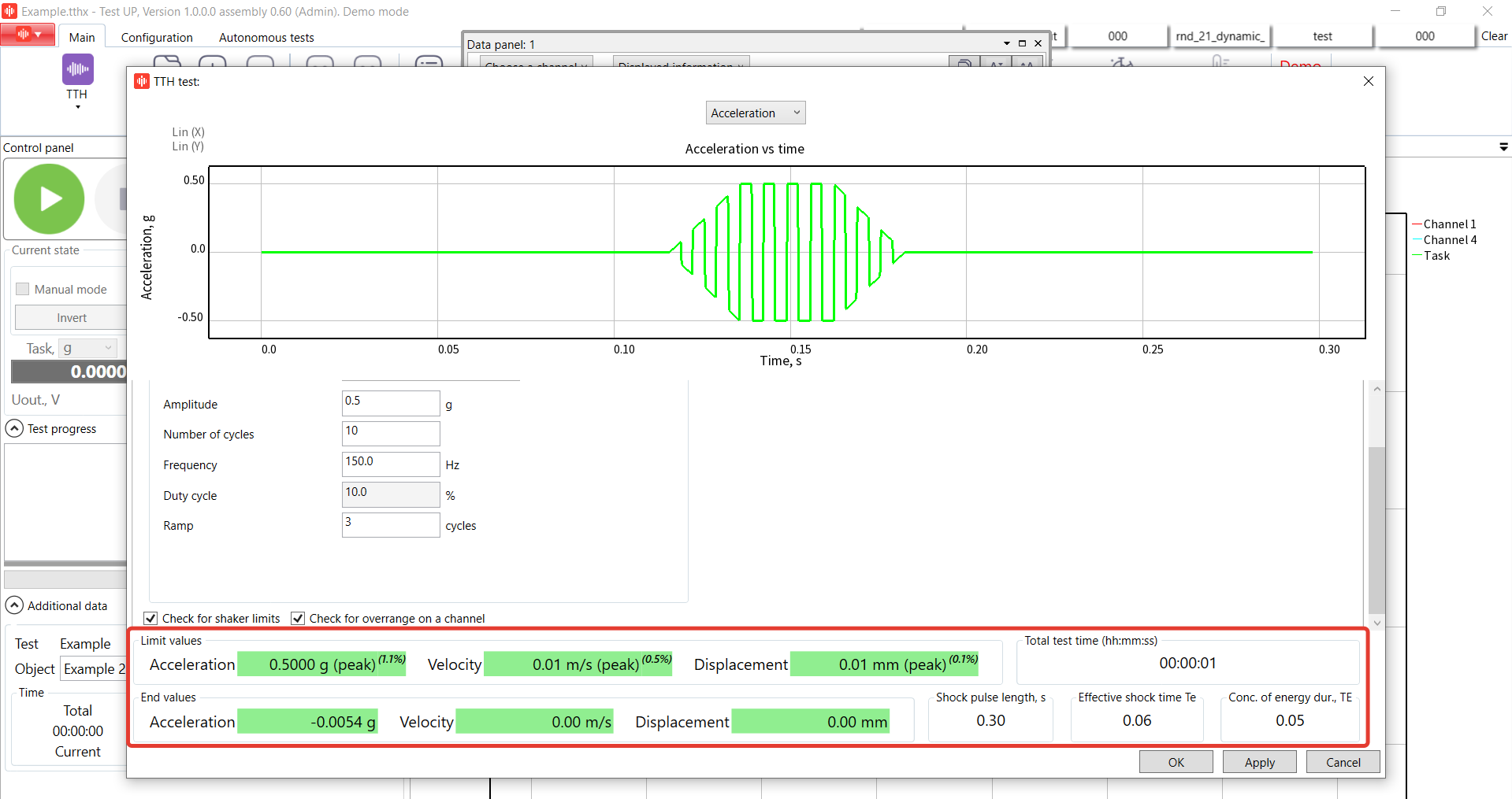
4. In the bottom of the profile tab you can see the maximum values for the profile, information about the shock duration and calculated TE upper parameter based on MILSTD standard.
5. Open ''SRS table'' tab and enable ''Use SRS table''. If the ''Use SRS table'' tab is active, the user can enter the parameters in it. Otherwise, the system does not use the data specified in it. In case that the box is not checked, the type of SRS synthesis ''SRS frequencies'' is not possible.
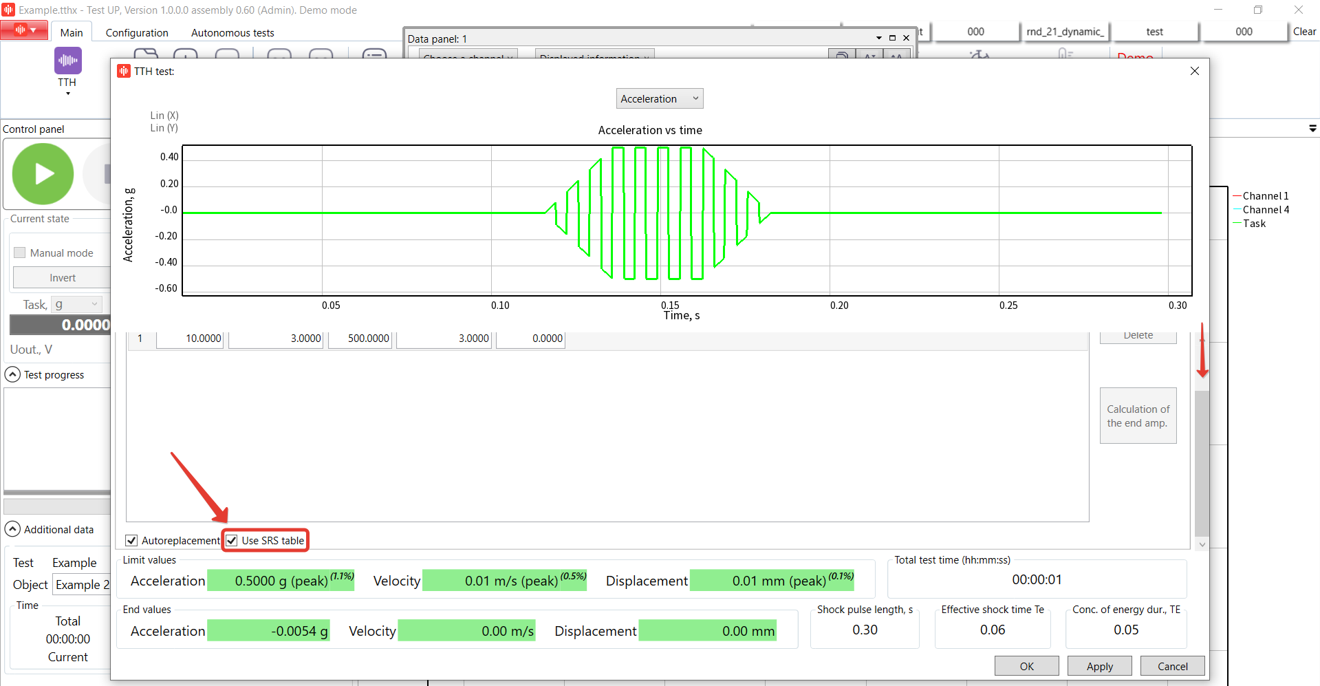
6. Enter the linear profile from 10 Hz up to 500 Hz at 3 g amplitude.
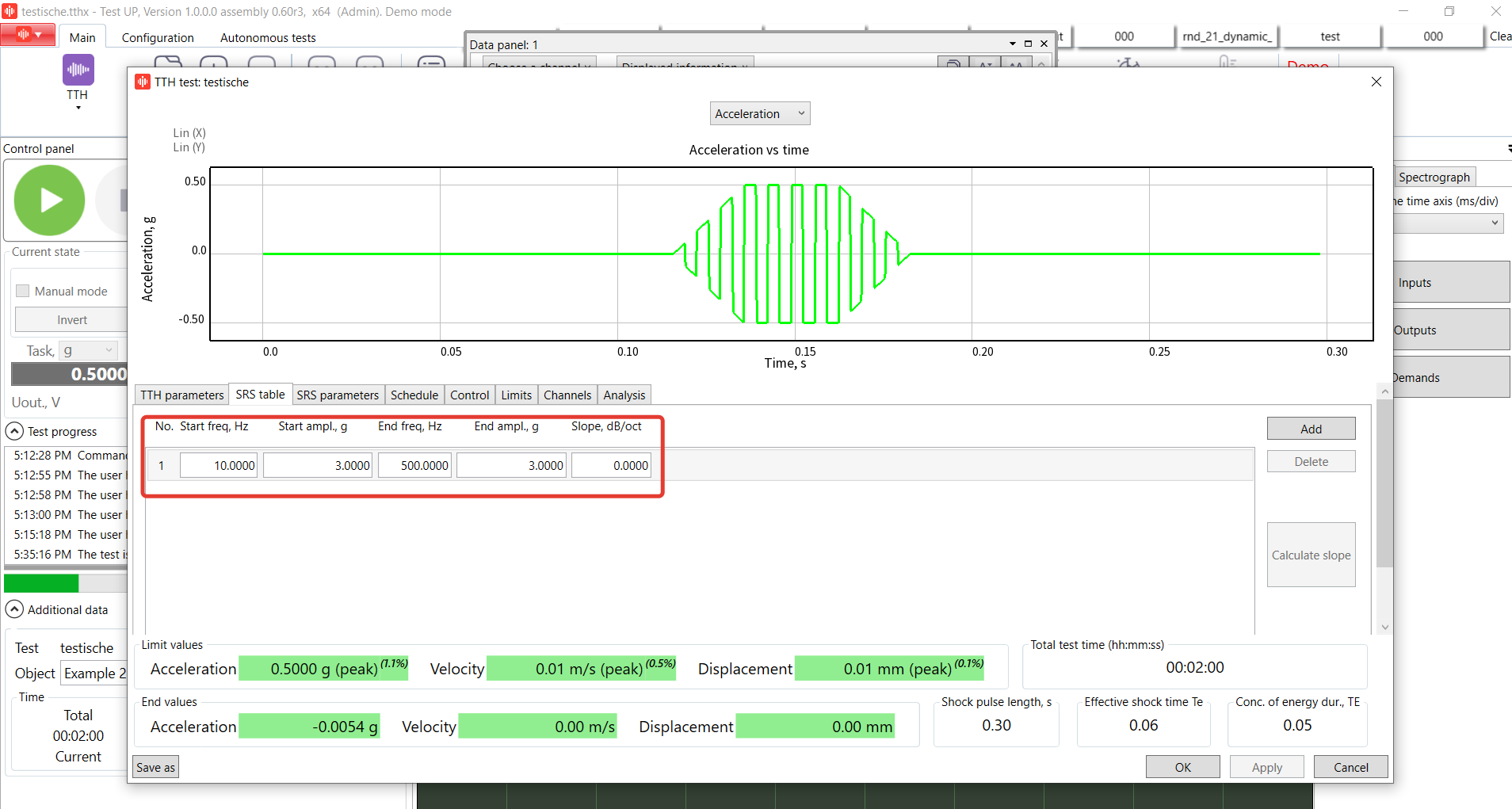
7. Open ''SRS parameters'' tab and enable ''Make SRS calculations'' option. In this case SRS will be calculated and you will be able to see the results on the graph. Learn more about SRS test type.
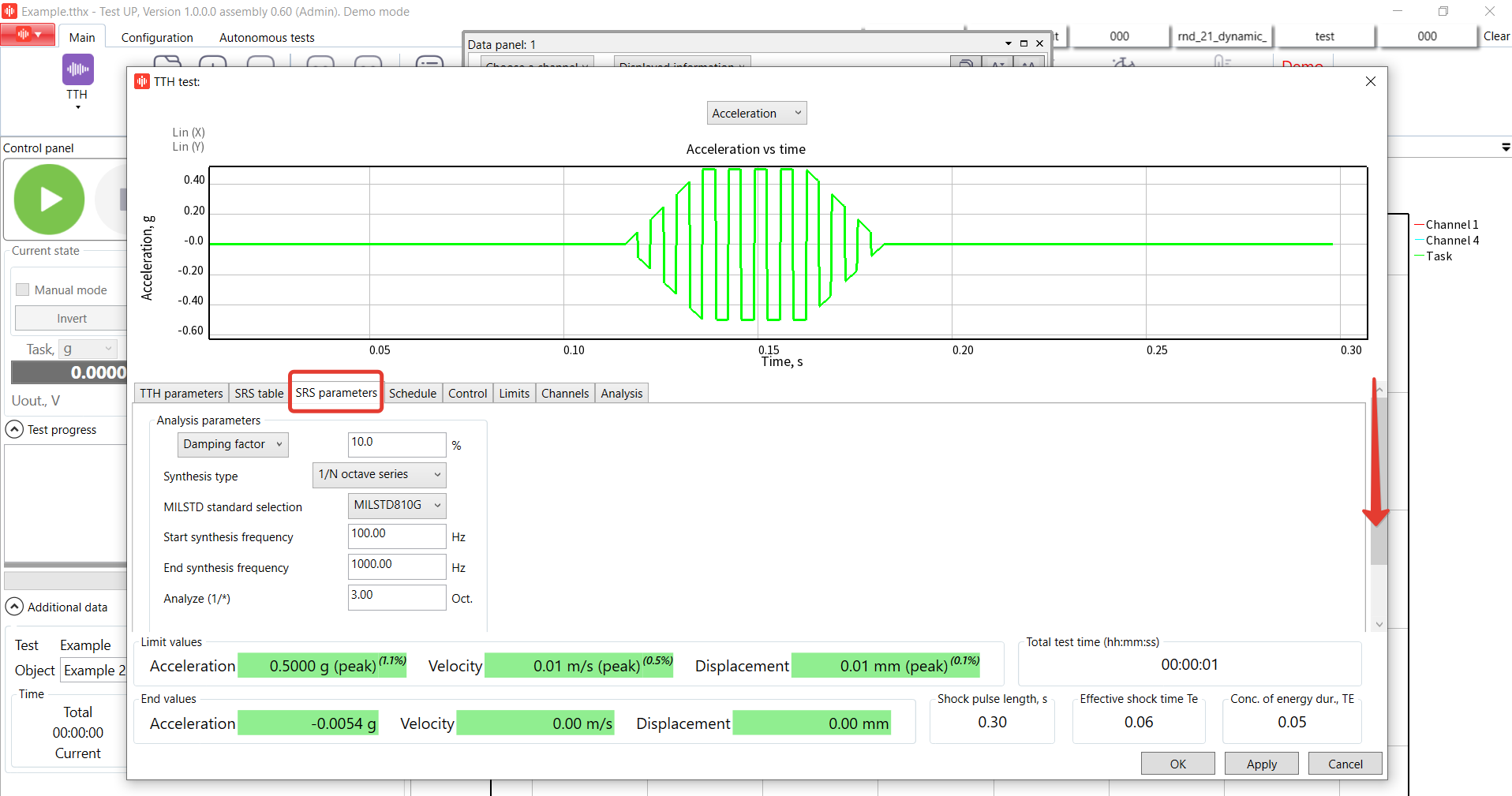
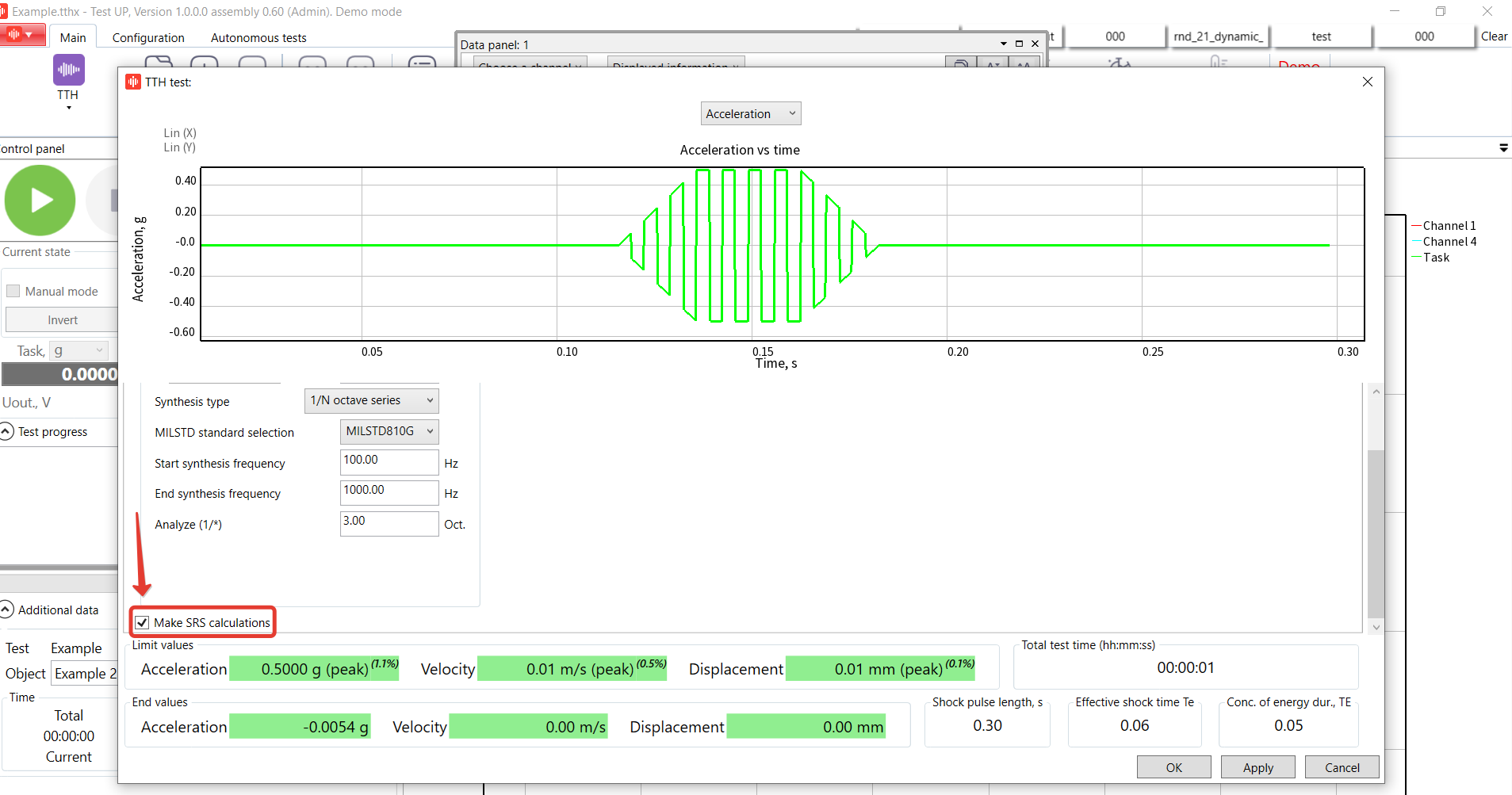
Leave the settings of SRS by default.
8. Open ''Schedule'' tab and add 2 commands. The schedule is a sequence of commands. Enter 10 shocks in the first and the second lines, and 100 shocks in the third one. Specify the schedule for each test you have. The schedule has to have at least one ''Shock'' command.
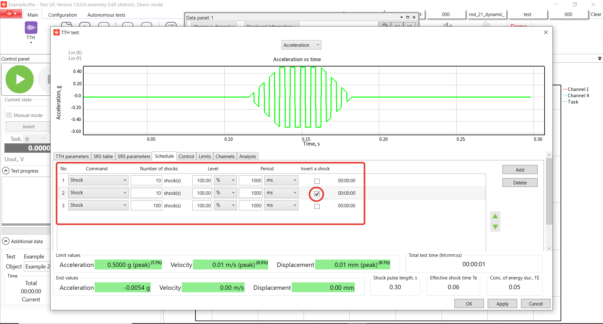
The Schedule in the TTH test type can include the following commands:
''Shock'' – on performing this command the controller periodically sends shock pulses with the parameters specified on the ''Pulse'' tab to the outputs.
! If the box ''Invert shock'' is checked, the controller inverts the shock direction, i.e. all the points of the profile are multiplied by ''-1''.
- ''Pause'' – temporarily pauses test progress, i.e. during this command no voltage is supplied to the controller’s outputs.
- ''Waiting for the user commands'' – when this command is performed, the system transfers to the mode of waiting for the user response and does not deliver voltage to the controller’s outputs. Until the ''Continue'' button has been pressed, the test will not be continued.
- ''Create a report'' – when this command is executed, a test report is created.
9. Open ''Control'' tab. Leave the main settings by default.
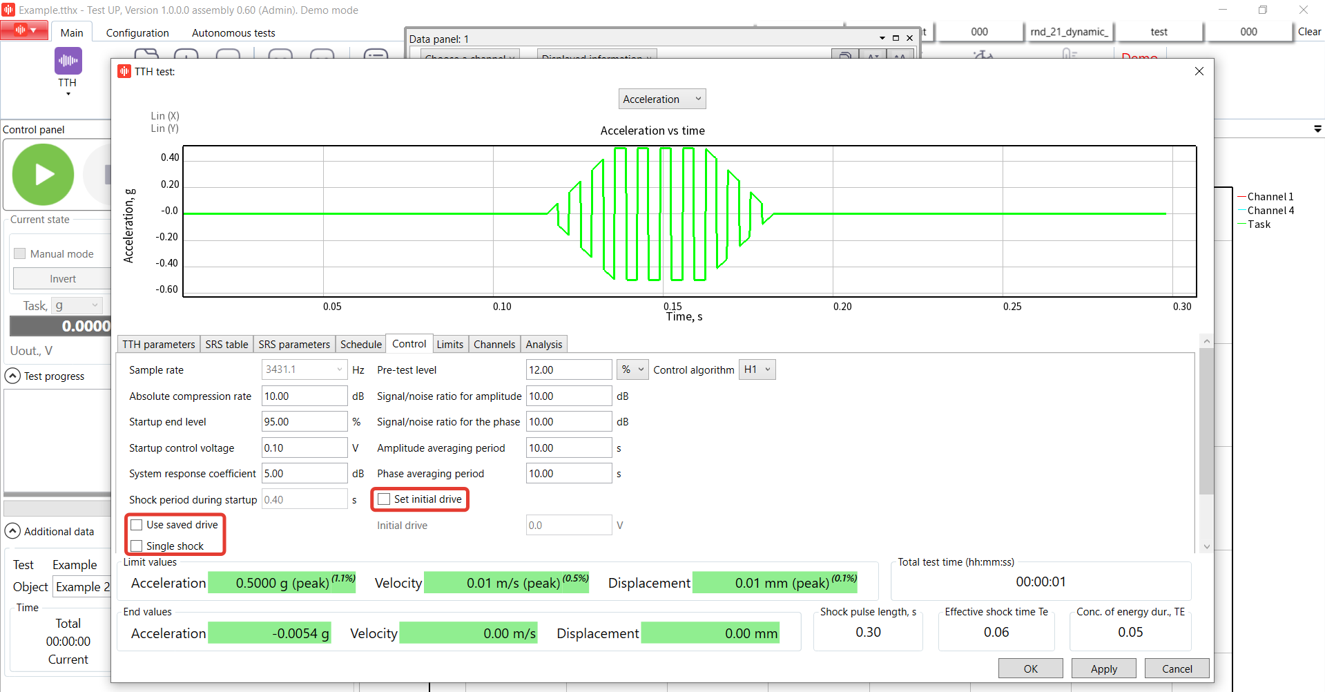
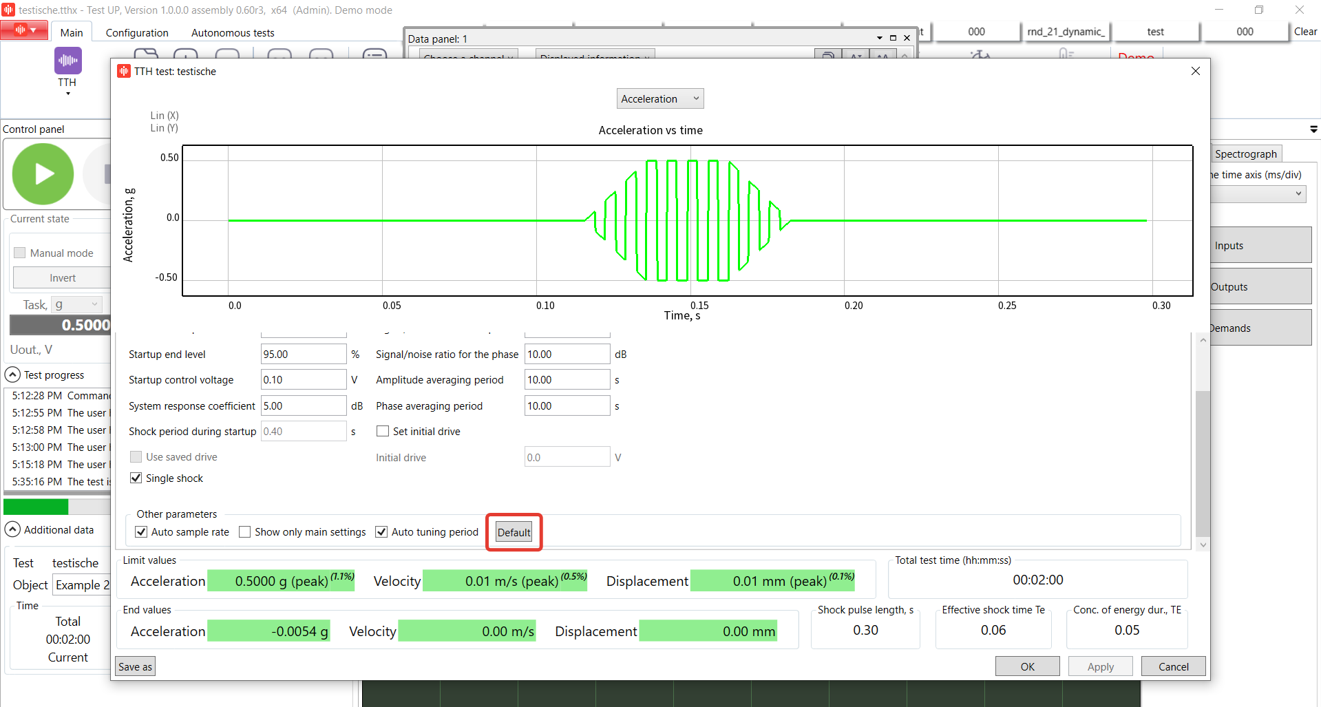
The “Control” tab contains a number of fields, to which the parameters are entered. Based on these parameters, the system controls the vibration test.
The “Default” button sets the values of all the parameters to be equal to those specified on the “TTH” tab of the “Control” tab of the “Default settings window”.
If the “Show only the main settings” checkbox is checked, only the most frequently used and critical control parameters are shown. Otherwise, all the available control parameters are represented. It is recommended to select only the basic test settings and use default settings for the rest of them. This box is checked by default.
We would like to pay your attention to the additional features:
- «Use saved drive» option is used to improve the start-up speed of your test if you’re running the series of identical tests using the same equipment.
- «Single shock option» increases the start-up time. Enabling this option the system won’t do any shocks during the start-up. If you enable this option, the system will enter the stable test mode faster after start-up, but shock adjustment will be disabled. That is why the system asks the user to confirm switching on this mode.
- «Set initial drive value» option is used while the start-up. Note, you should know this value and be careful with this parameter. Presumably safe start voltage delivered to the controller output for start up acceleration during the test (the parameter can be specified if the “Set initial drive” checkbox is checked).
10. Check the shaker manufacturer in the limits tab. Leave it by default.
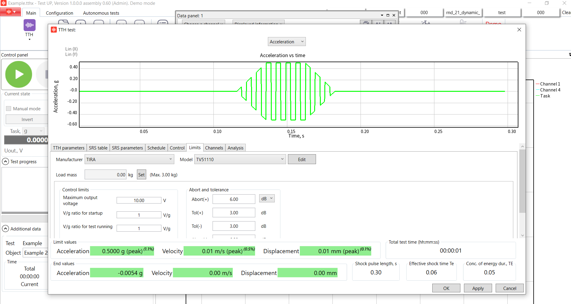
11. Set channels configuration in the Channels tab. Leave it by default.
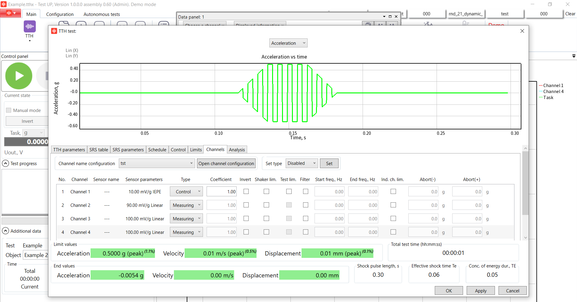
12. Start the test!
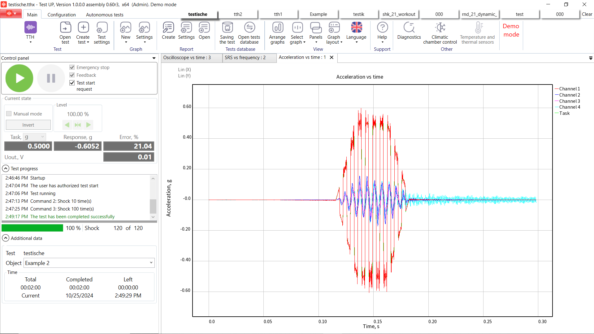
If the current command is “Shock”, the system first makes attempts at startup before reaching the level of startup end and then performs the test. Startup is always performed on a non-inverted shock, despite pressing the “Invert” button on startup or checking the “Invert a shock” checkbox in the current command of the schedule. If startup failed, the test stops and the reason for the stop appear on the test log.
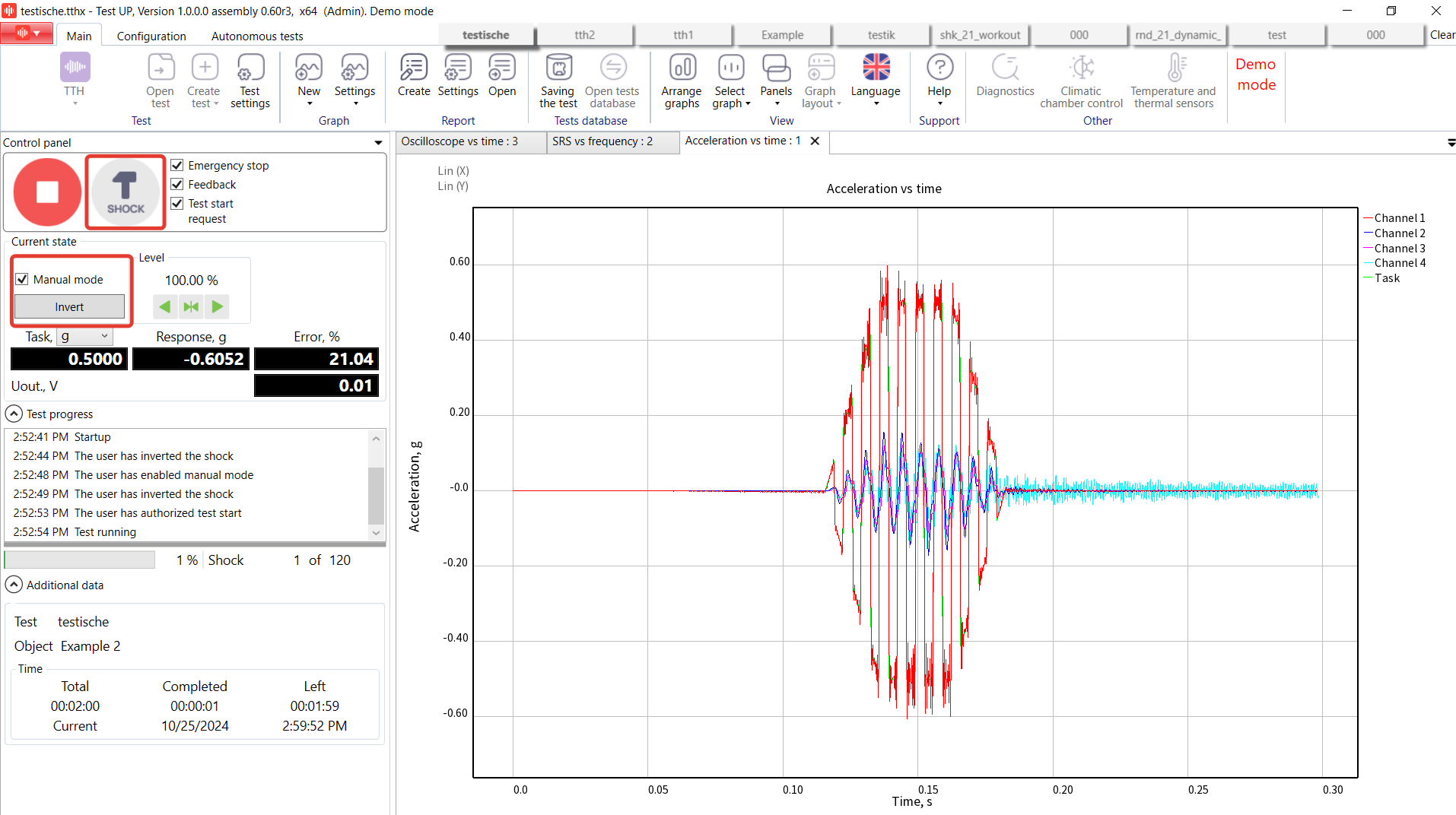
On pressing “Invert”, the controller inverts the direction of shock, i.e. all the points of the shock profile will be multiplied by “-1”. After 10 shocks in the first command are done, we can see an inverted shock. After we have performed all inverted shocks, we switch the manual mode and press the button to perform a shock.
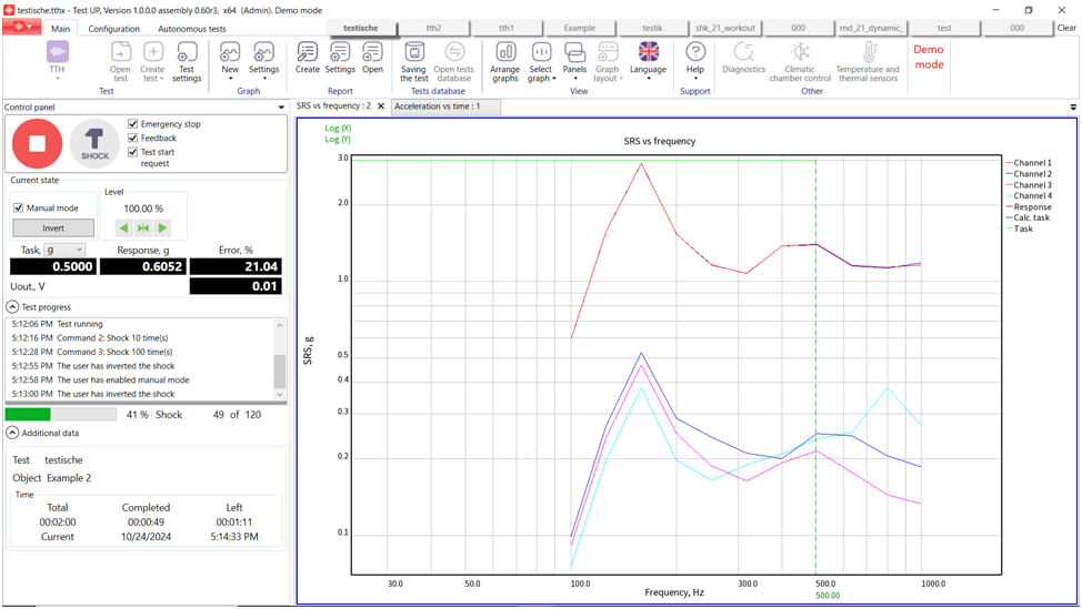
Let’s take a closer look to additional tabs: Oscilloscope and SRS vs Frequency graph.
The “SRS from frequency” graph enables representing the following shock spectra:
- “Reference” (“Task” line) – the one specified on the “SRS table” tab of the test settings window; this line is only shown if the box “Use SRS table” is checked on the tab “SRS table” of the test settings window;
- Calculated SRS (the “Calculated task” line) – the SRS calculated based on the parameters specified on the “SRS parameters” and “Zero offset parameters” tabs of the test settings window;
- Channels SRS (lines with channels names) – shock spectra based on the data obtained from the controller’s channels.
The “Oscilloscope” – graph type, which enables displaying oscilloscope and spectrograph. It is a special type of graphs, as its window is different from the windows of other graph types. Only one oscilloscope graph can be created. The “Axes” panel is not available for oscilloscope, as the scale of horizontal and vertical axes of oscilloscope is set in the oscilloscope display window. Besides the channels, the data from the controllers’ outputs connected to PC can be displayed for oscilloscope.

RULA offers top-of-the-line controllers and TestUp software for your needs, making it easy to conduct such advanced test types as TTH. To learn more about TTH test running, watch our video below.
If you want to get more details or an offer for TTH test type, please send us an email to contact@rula-tech.com.


