

Previously, we explored the fundamentals of Shock Vibration Testing, covering its basic theory, pros and cons, international standards, features available in TestUp, and advanced shock testing methods: SRS and TTH. Today, we are discussing the complexities of Shock Response Spectrum.
SRS testing is applied in the various fields:
- Aerospace Engineering: to simulate the dynamic response of aircraft and spacecraft to shock events such as turbulence and sonic booms;
- Earthquake Engineering: to simulate the dynamic response of buildings and bridges to earthquake shaking;
- Transportation: to simulate the dynamic response of vehicles and infrastructure to shock events such as crashes and road hazards.
SRS test type usually is used for transient event description, damage potential estimation, structural design, research.


Purpose of SRS test type
SRS test type is used to characterize the frequency response of shock environment to estimate the maximum dynamic response to structures. It aims to produce and excite several different oscillations and resonance frequencies inside the DUT. These calculations can follow an arbitrary list of frequencies, but usually a certain n-octave range is taken for this purpose (third-octave, quarter-octave, etc.), depending on the technical task.
Benefits of SRS Testing
SRS testing offers several benefits, including:
- Improved accuracy: SRS testing allows for more accurate simulation of real-world shock events.
- Increased efficiency: SRS testing can be used to test multiple scenarios quickly and efficiently.
- Reduced costs: SRS testing can help reduce costs by identifying potential issues early in the design process.
Main SRS principle
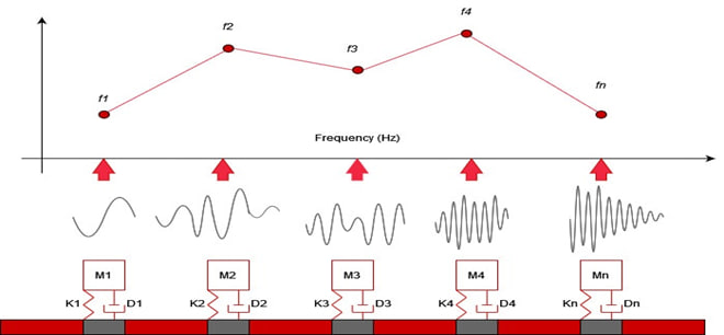
The main SRS principle is based on representation of time domain data in the frequency domain. SRS models waveform response channels using a set of theoretical single-degree-of-freedom mass-damper-spring accelerators. The horizontal axis of the plot represents the natural frequency of each single-degree-of-freedom. The theoretical response of each single-degree-of-freedom is plotted on the vertical axis. It is important to note that SRS is not an actual response of an object under test but only the theoretical representation of the response.
How to conduct SRS vibration test in TestUp?
To conduct SRS vibration test in RULA software TestUp, engineers need to define the appropriate test profile based on relevant standards or specific DUT requirements. These profiles are defined to replicate the specific shock events that a product may experience in its intended application. The key parameters of the SRS test profile include SRS table, synthesis type, wavelet table and analysis parameters.
Guide to SRS test type in TestUp
In TestUp software, SRS vibration test is set up and run in a few simple steps, as you can see in the screenshots below.
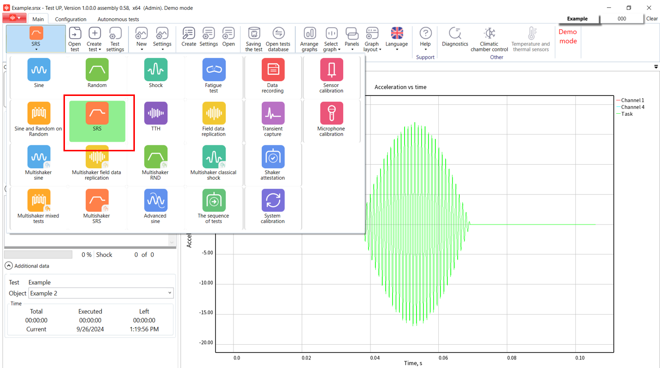
Step 1. Choose «SRS» test type in TestUp.
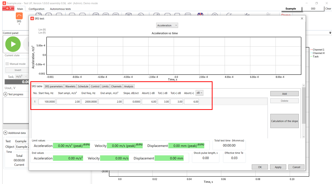
Step 2. Press «Create a new test» button and enter the parameters.
Note: On the right side, there is a button that can recalculate a value for the amplitude and the slope parameters.
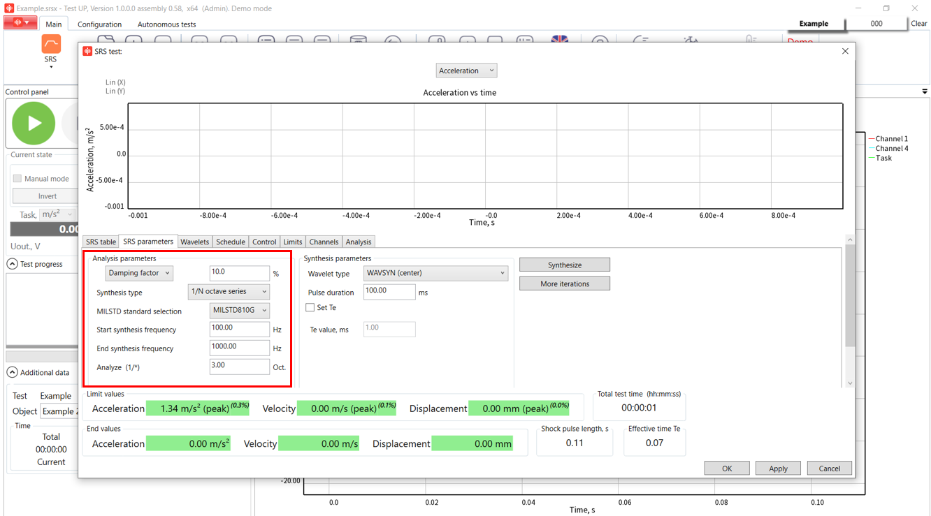
Step 3. Enter SRS parameters in two settings groups:
- Analysis parameters
Set a value for damping factor or a Q-factor for the shock. The damping factor characterizes the speed of amplitude decreased during the shock, whereas the Q-factor characterizes the waveform, sharpness, and its quality.
- Synthesis type
Select a wavelet type from the options: octave series, wavelet frequencies, SRS frequencies, or a linear step. If you select the «octave series» option, you will need to specify the MIL-STD standard, start and end frequencies of the synthesis, and the part of an octave to analyze. The second option uses the frequencies from the Wavelet tab, the third uses frequencies from the profile tab, and the last option allows the user to specify a linear frequency step for analysis.
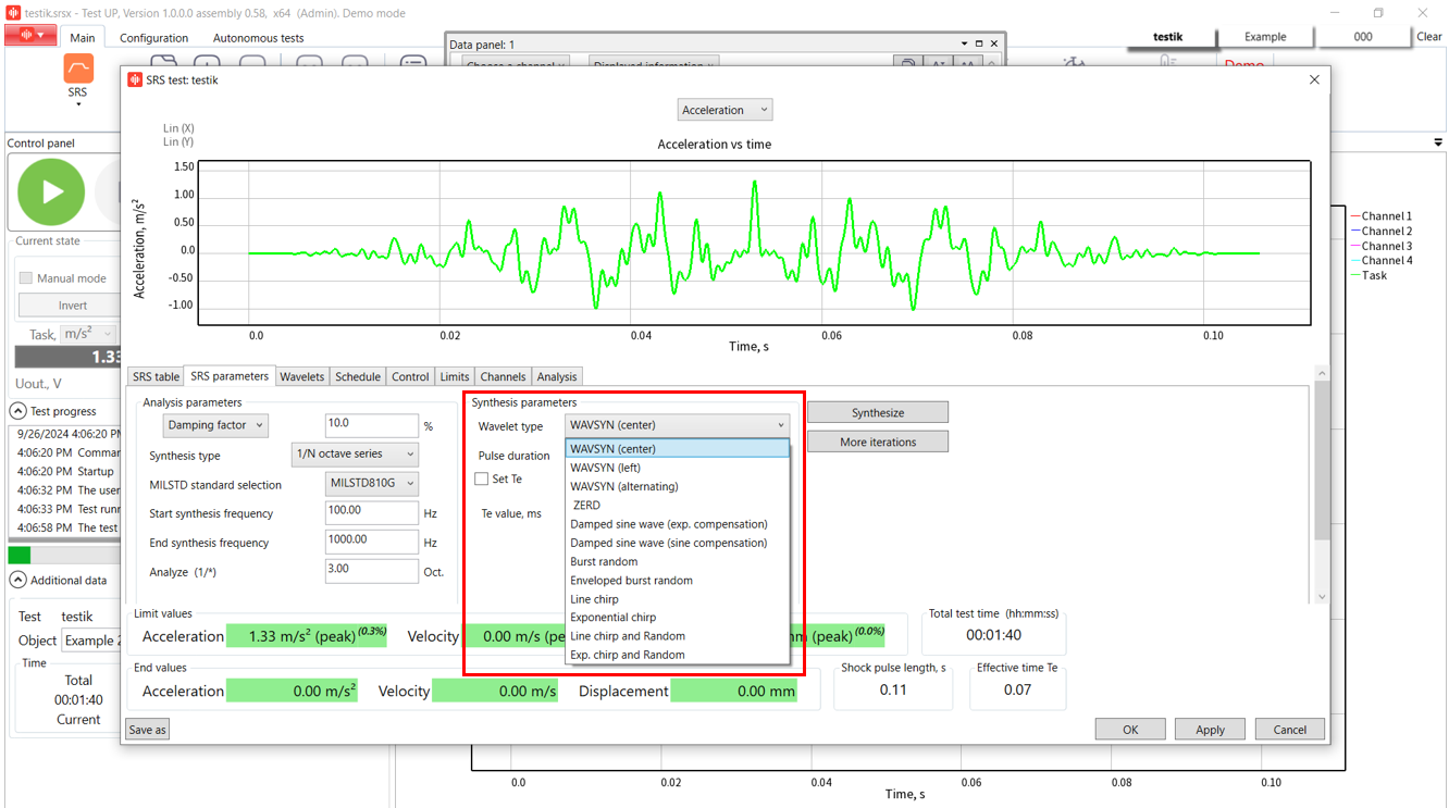
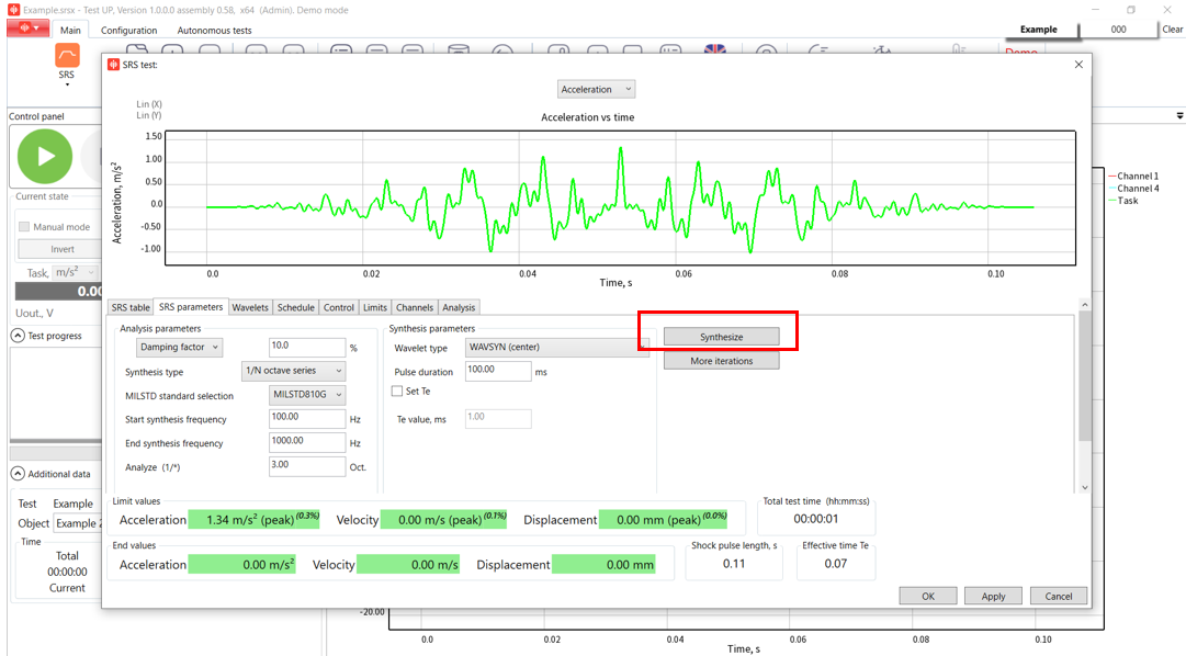
Step 4. Enter synthesis parameters.
TestUp offers a wide variaty of wavelet types:
- WAVSYN (center);
- WAVSYN (left);
- WAVSYN (alternating);
- ZERD;
- Damped sine wave (exp. compensation);
- Damped sine wave (sine compensation);
- Burst random;
- Enveloped burst random;
- Line chirp;
- Exponential chirp;
- Line chirp and Random;
- Exp. chirp and Random.
Step 5. Enter Pulse Duration
According to the selected MILSTD standard, the user can enter either TE lower or TE upper, where TE lower represents the effective short duration, and TE upper is the minimum length of time that contains all time history magnitudes exceeding in absolute value one-third of the shock peak magnitude absolute value. After that, we press the “Synthesize” button and see the resulted signal. Also, we can add more synthesis iterations.
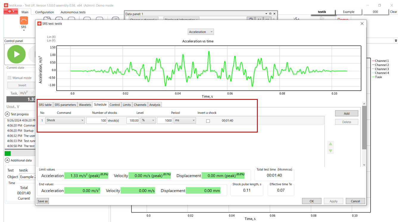
Step 6. Open «Schedule» tab and enter the desired shock number, level, period between the shocks, and invert a shock.
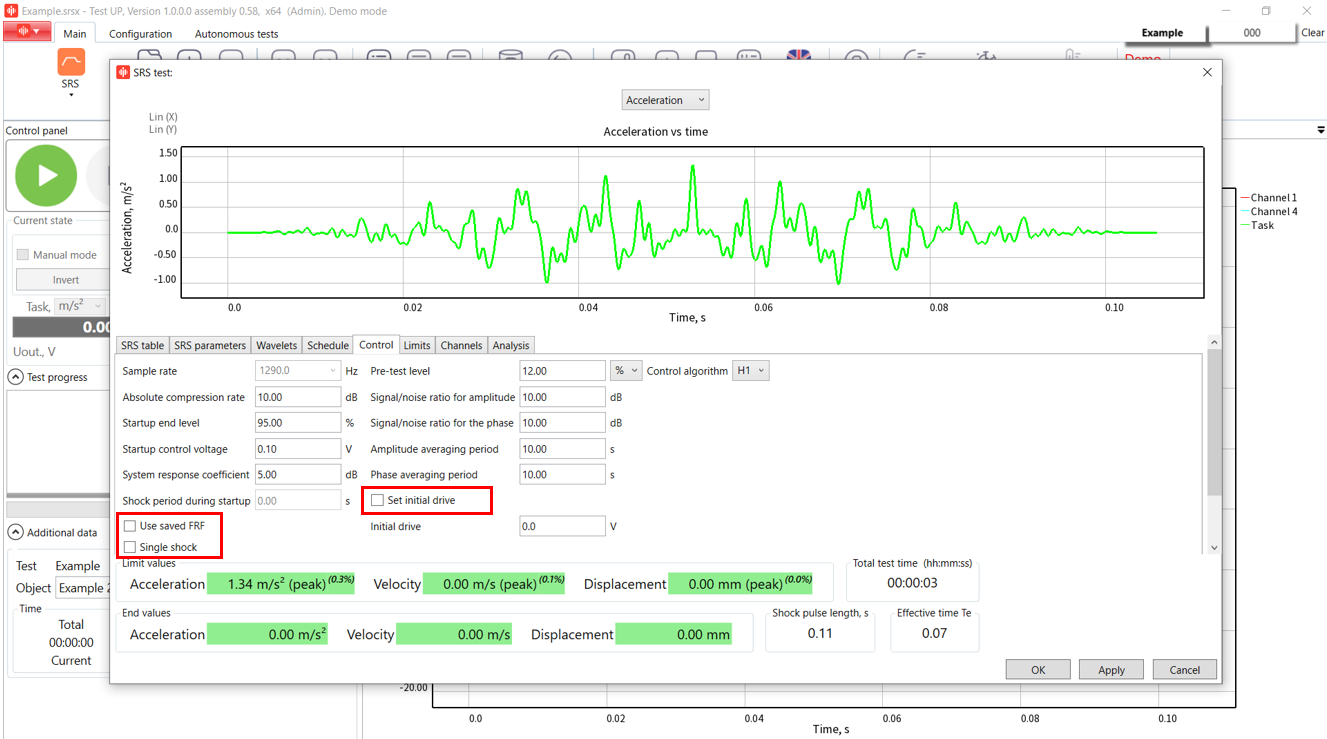
Step 7. Enter the parameters in the Control Tab
“Used saved FRF” option is recommended to enhance the startup speed of the test if the user is running a series of identical tests using the same equipment.
In contrast, the “Signal shock” option increases the startup time, and unable the system to do any shocks during the startup. Additionally, the user can set the “Initial drive value” which will be used during the startup process. Keep in mind that you need to be really careful with this parameter to ensure accurate test results!
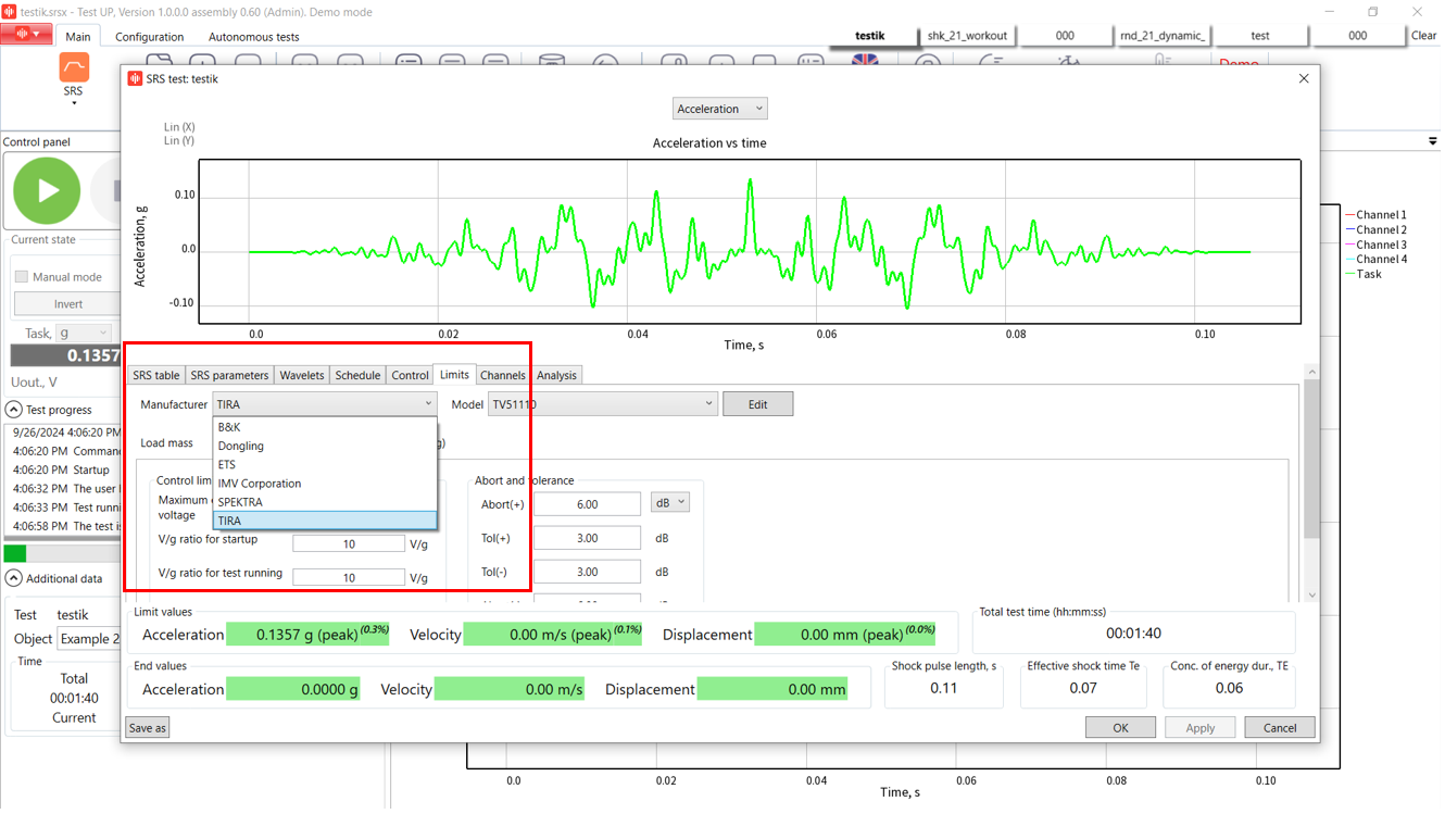
Step 8. Select the shaker manufacturer and check the configuration on the channels tab. Start the test!
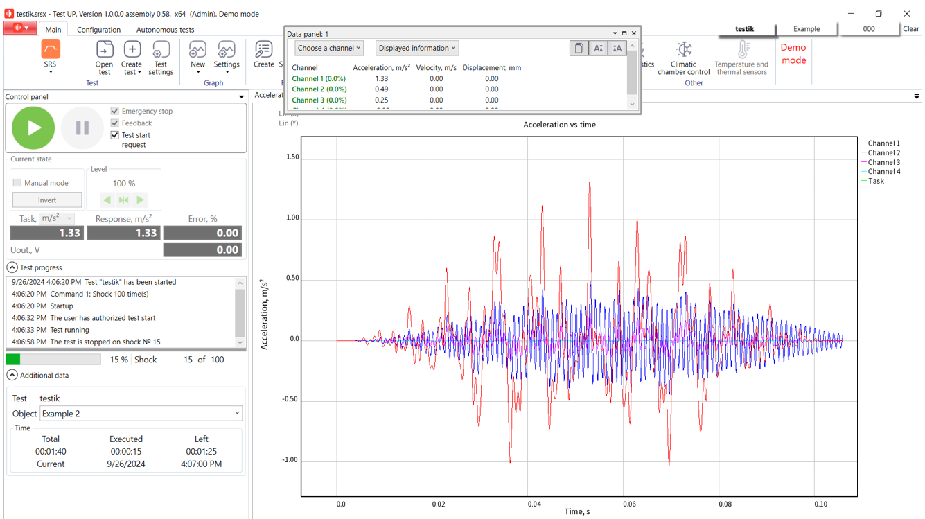
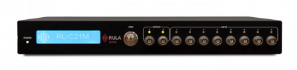
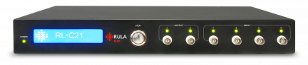
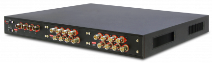
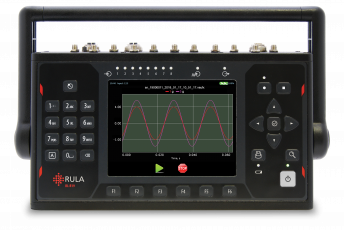
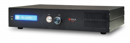
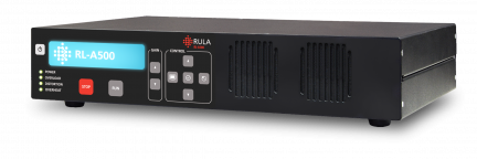
RULA offers top-of-the-line controllers and TestUp software for your needs, making it easy to conduct such advanced test types as SRS. To learn more about SRS test running, watch our video below.
If you want to get more details or an offer for SRS test type, please send us an email to contact@rula-tech.com.