


The procedure of shock sensor calibration is applied when the amplitude characteristics of the sensor are to be determined. ISO 16063-22 is the main standard for the shock calibration procedure. It describes the process, the scope and provides examples of different shock machines usage.
According to the standard ISO 16063-22 the procedure of shock calibration can be performed using different types of shock machines: pendulum shock calibrator, dropball shock calibrator, pneumatically operated piston shock calibrator, and Hopkinson bar shock calibrator.
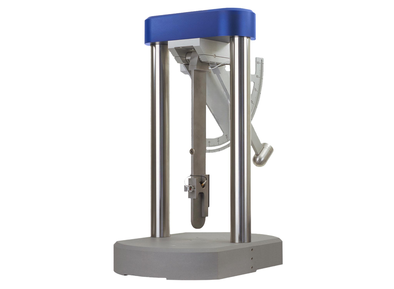
Pendulum shock calibrator
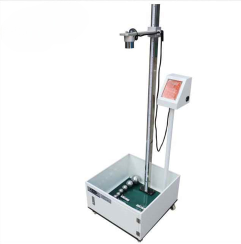
Dropball shock calibrator
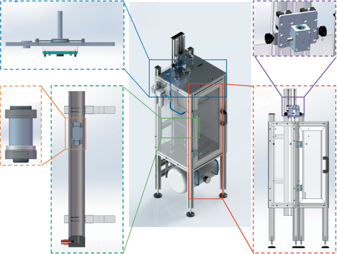
Pneumatically operated piston shock calibrator
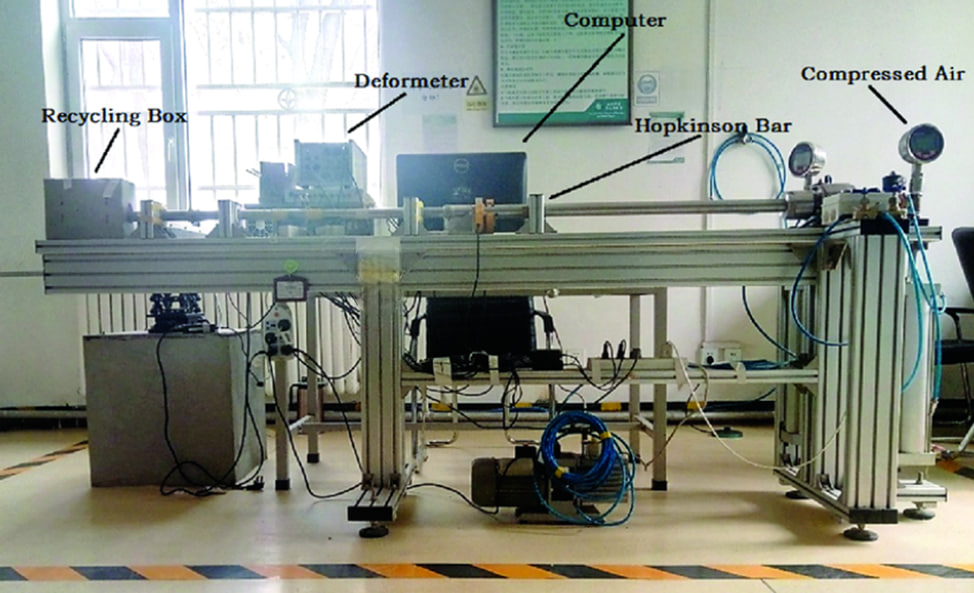
Hopkinson bar shock calibrator
Schematic diagram of shock calibration setup
Let’s take a closer look at the shock calibration setup, using the pendulum shock calibrator as an example. The pendulum shock calibrator allows the user to determine the shock sensitivity and amplitude linearity over a wide range of accelerations.
Comparison calibrations are performed at accelerations ranging from 100 m/s2 to 1 500 m/s2 (10 gn to 150 gn) at half-sine pulse durations (measured at 10 % magnitude) from 3 ms to 8 ms. The shock pulse duration, T, is dependent on the acceleration peak value, i.e. 3 ms at 1 500 m/s2 and 8 ms at 100 m/s2. Amplitude linearity may be measured over 4 to 7 impacts of the pendulum system, or with a number of single shock pulses at different acceleration magnitudes.
The pendulum shock calibrator consists of a rigid frame, a hammer pendulum, and an anvil pendulum. Typical dimensions for the frame are approximately 500 mm by 500 mm for the square base plate and 780 mm height. The mass of the whole construction is approximately 60 kg. The length of anvil pendulum is approximately 400 mm.
The reference accelerometer and the accelerometer under check are mounted on the anvil as shown in the illustration below.
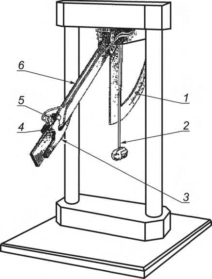
Illustration 1. Pendulum shock machine
(1 - Graduated scale with adjustable end stop; 2 – Hammer pendulum; 3 – Rubber pad; 4 - Reference accelerometer; 5 – Accelerometer under check; 6 – Anvil pendulum)
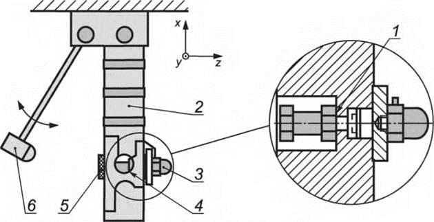
Illustration 2. Correct mounting of accelerometers and selection of the reference surface for the reference accelerometer for pendulum shock calibrator
(1 - Reference and measurement surface used for primary calibration; 2 – Anvil pendulum; 3 – Accelerometer under check; 4 - Reference accelerometer; 5 - Butadiene rubber; 6 – Hammer pendulum)
Two accelerometers - reference and accelerometer under check, are mounted on the anvil as shown in Illustration 2. All surfaces on which accelerometers are mounted shall be polished, flat and clean.
This setup is used to reproduce the shock. The reference accelerometer records the amplitude of the shock, the accelerometer under check reproduces the charge/voltage.
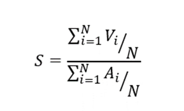
The process typically consists of five shocks. The peak values of V - for the accelerometer under check and A - for the reference accelerometer, are determined by analysis of both signals. The sensitivity of the accelerometer under check is calculated using the formula below:
The steps described above are repeated for several amplitudes.
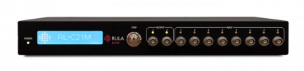
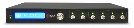
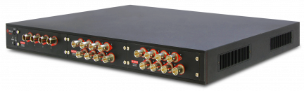
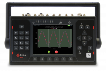
For shock sensor calibration RULA RL-C21 and RL-C25 vibration control and data acquisition systems can be applied.
How to conduct shock calibration in TestUp?
The process of shock sensor calibration can be divided into two parts. First, we need to perform a series of high-amplitude shocks. Second, we need to compare the results with the reference accelerometer data. In TestUp software, shock calibration is set up and run in a few simple steps, as you can see in the screenshots below.
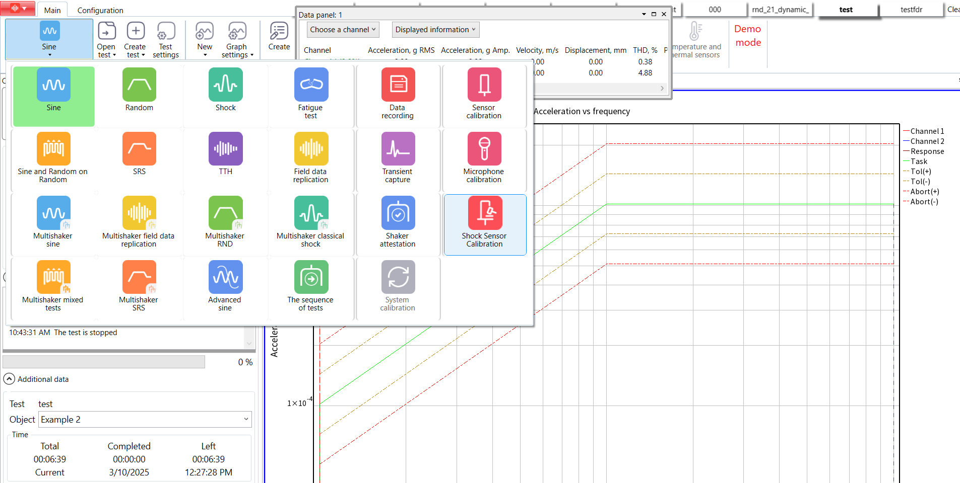
Step 1. Open TestUp and choose «Shock Sensor Calibration» test type.
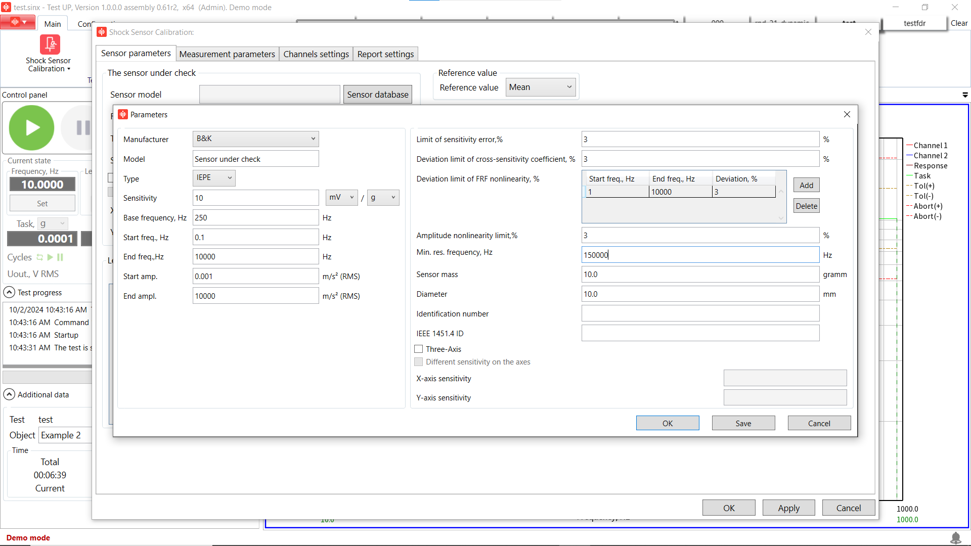
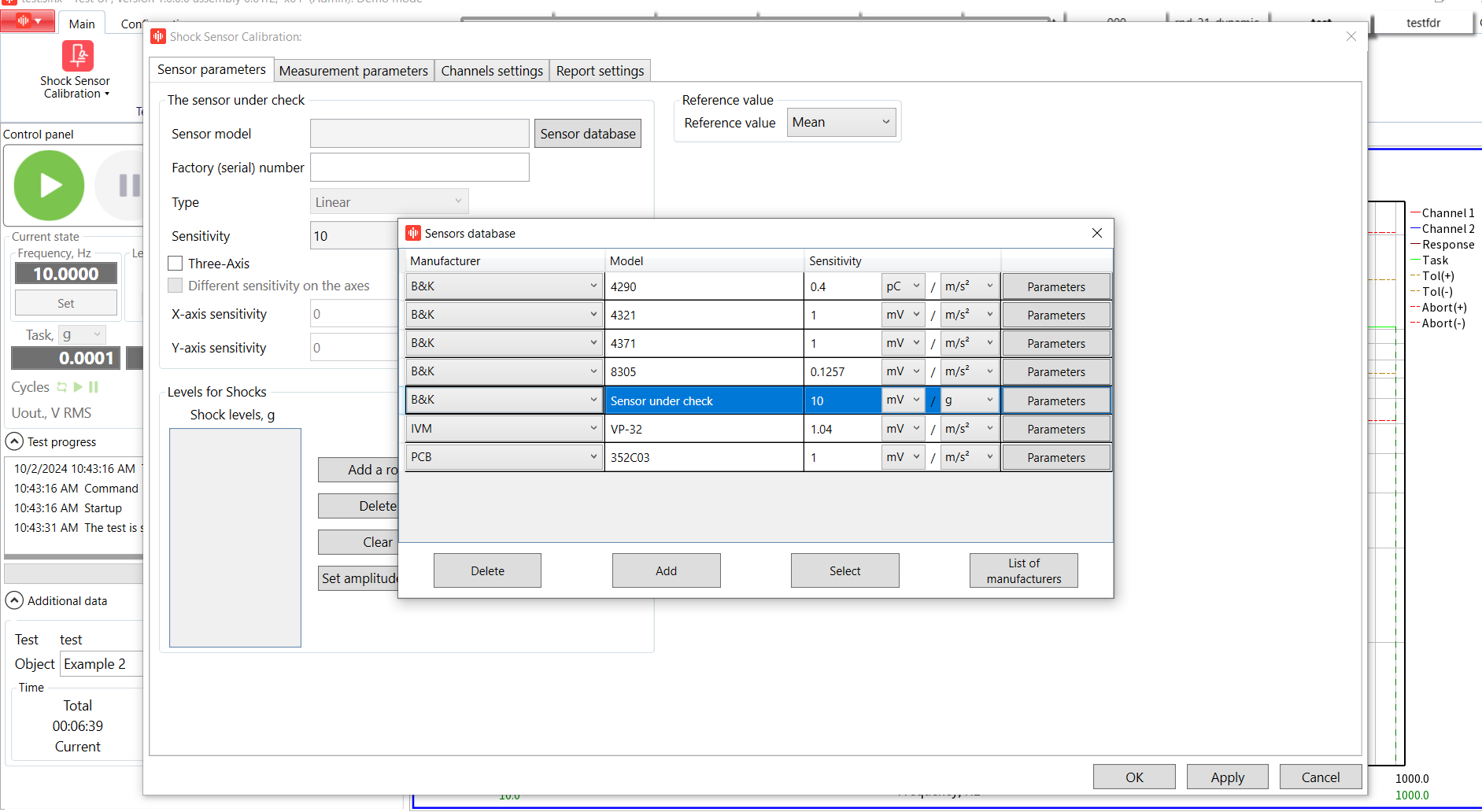
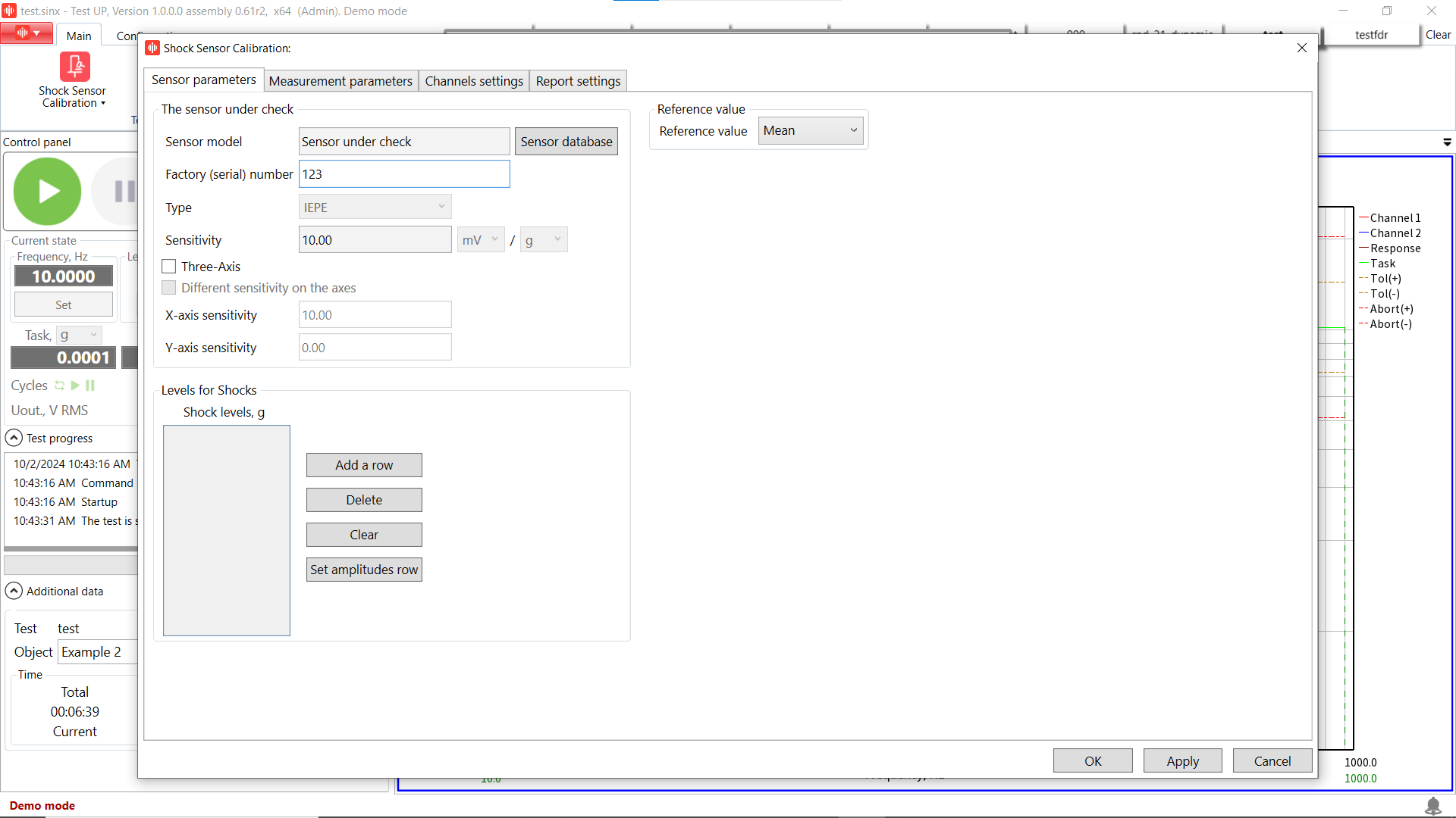
Step 2. Select the «Sensor parameters» tab and fill in the individual parameters of your sensor under check according to its datasheet.
Step 3. Add accelerometer’s under check serial number.
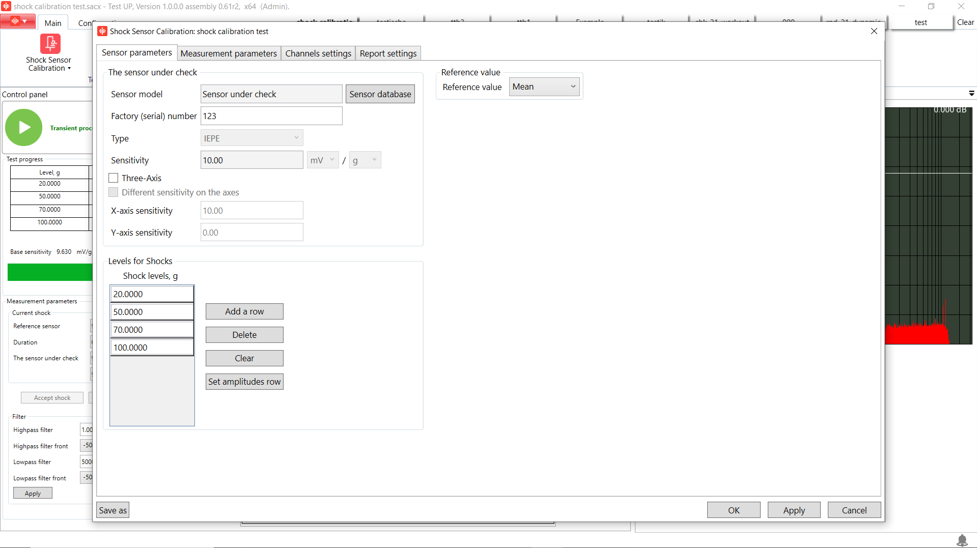
Step 4. Add shock levels in compliance with the amplitude range min and max values. For our sensor we set the following shock levels: 20 g, 50 g, 70 g and 100 g.
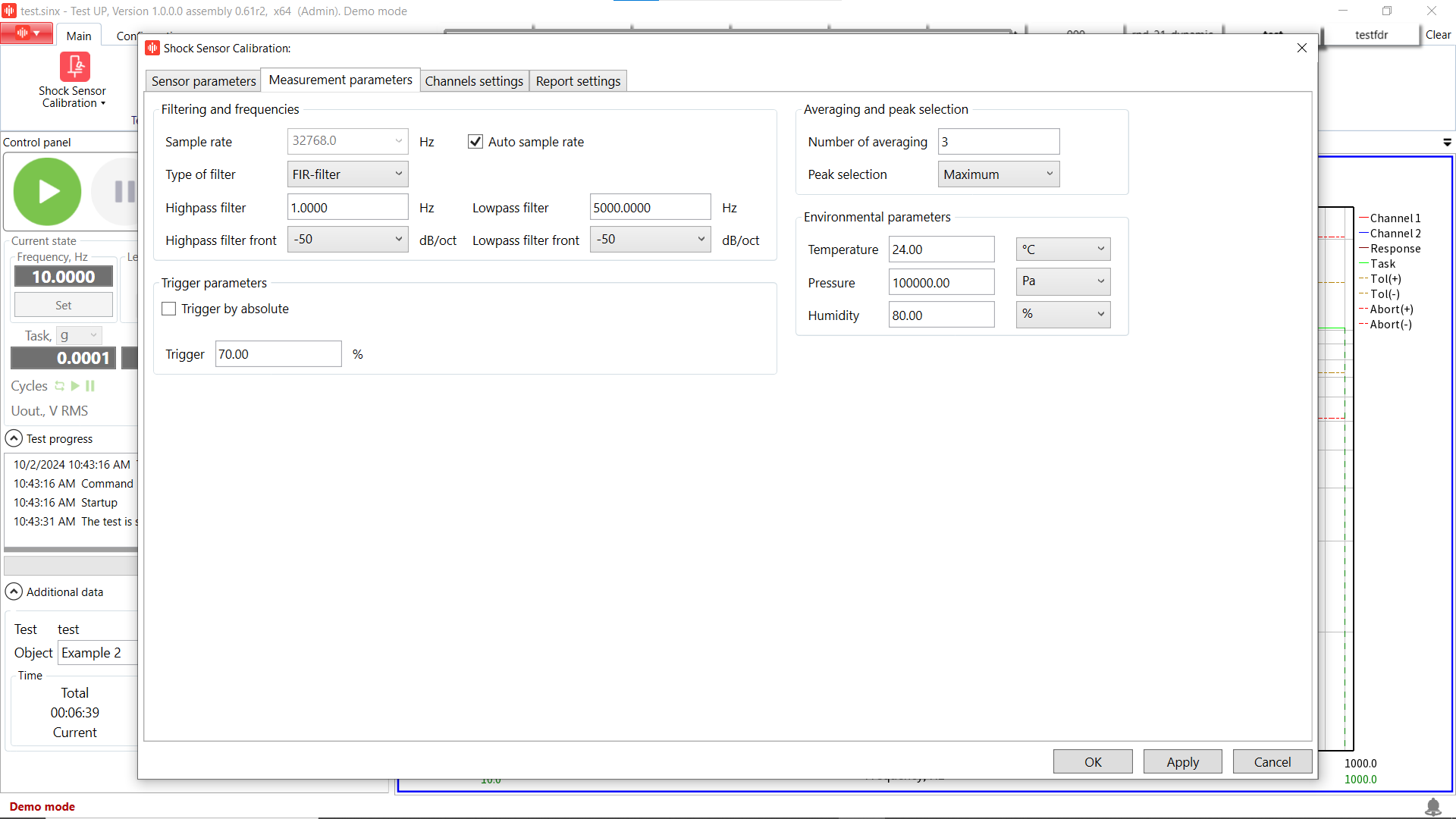
Step 5. Add measurement parameters. The number of averaging indicates the number of shocks you need to apply for each level.
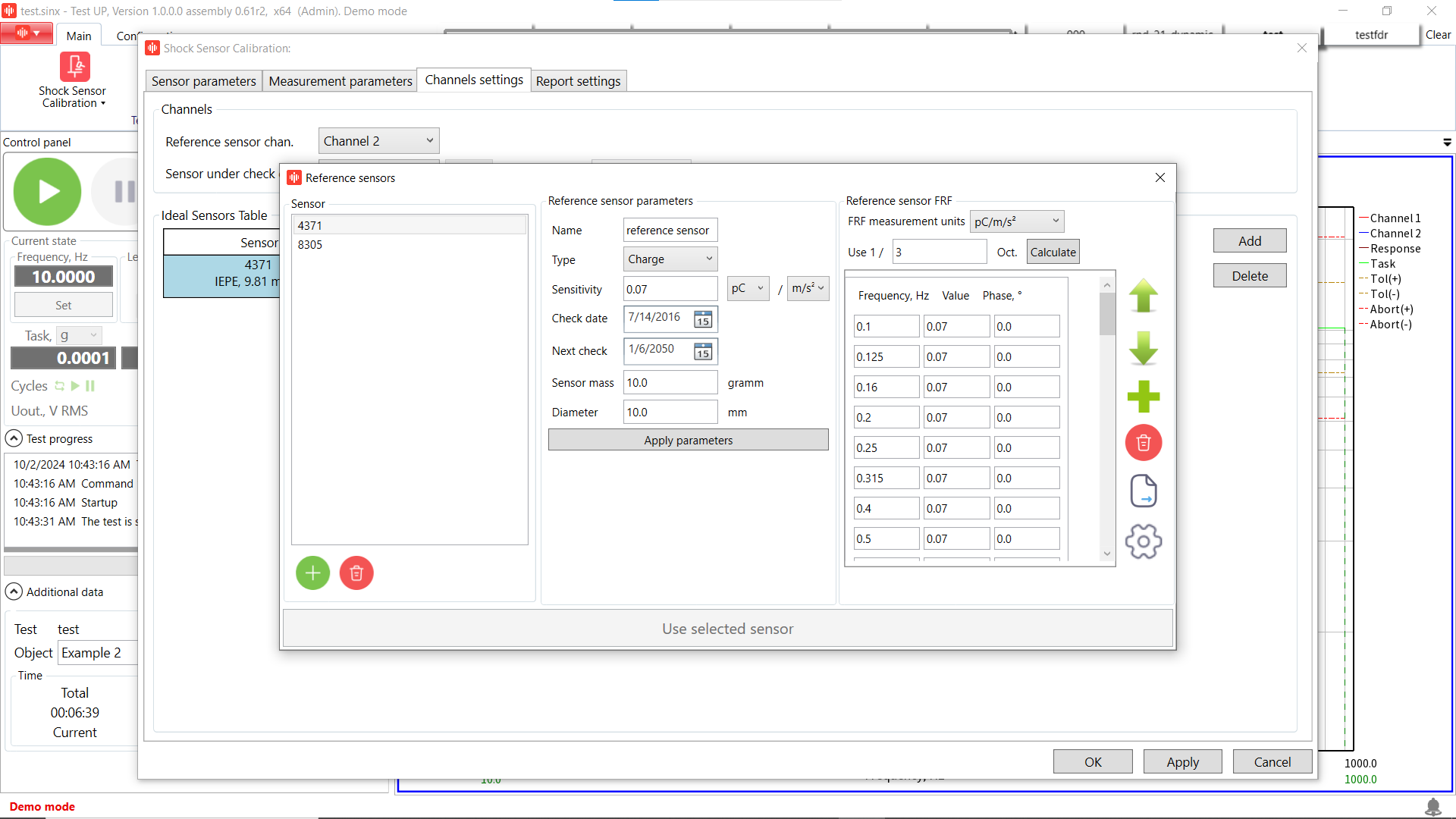
Step 6. Open «Channel settings» tab and add reference accelerometer parameters. Fill in sensor type and sensitivity value according to the passport of the sensor.
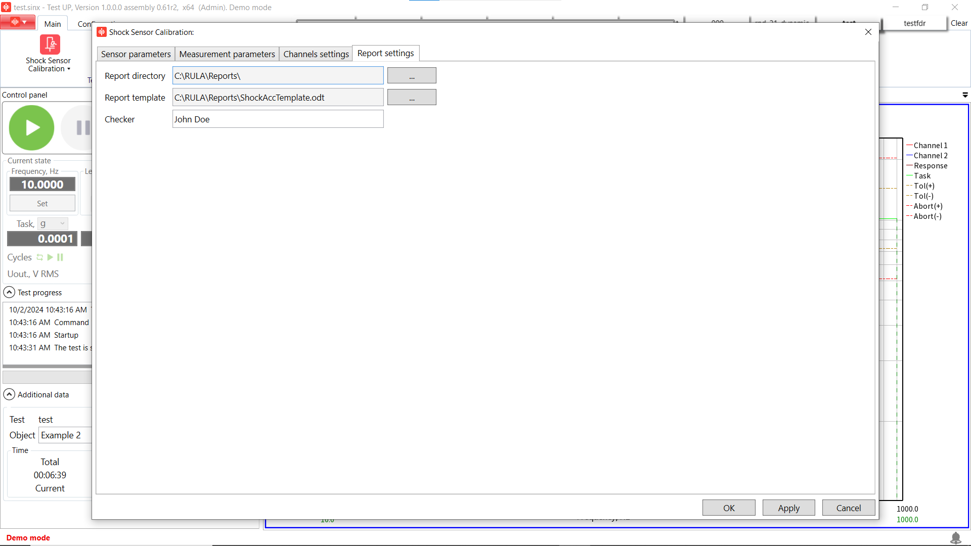
Step 7. Add report settings.
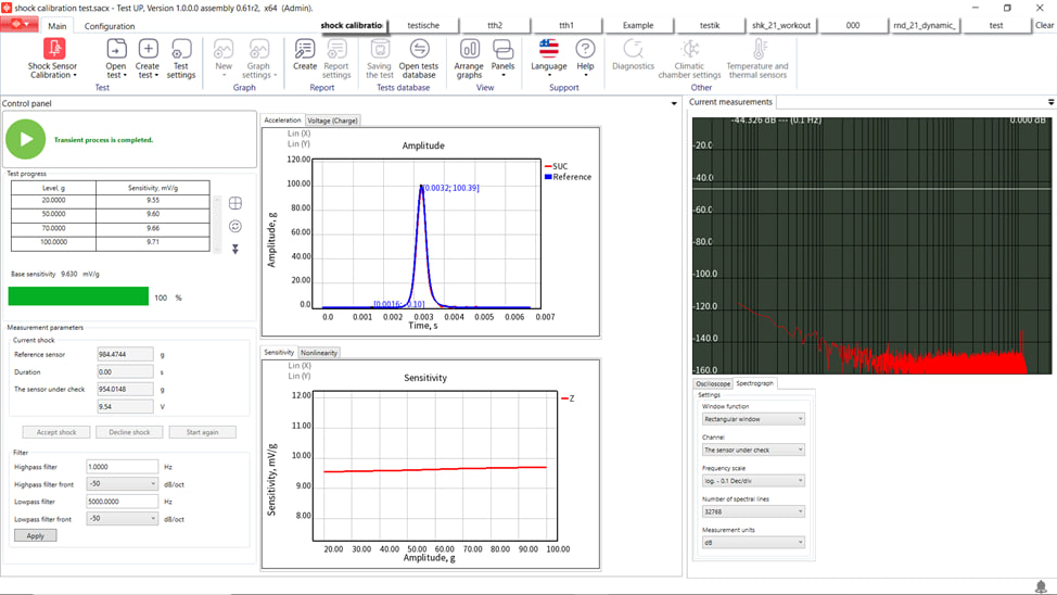
Step 9. The settings are complete and we can run the test! Review the result and compare the average sensitivity of the accelerometer under check with the reference accelerometer passport data.
RULA offers top-of-the-line controllers and TestUp software for your needs, making it easy to conduct such test types, as shock sensor calibration. Watch our webinar to learn more.
Still wondering why you should choose RULA software for shock sensor calibration?
Advantages:
- Supports all types of shock machines: pneumatically operated piston shock calibrator, pendulum shock calibrator, dropball shock calibrator, and Hopkinson bar shock calibrator;
- Provides easy and fast results: place the accelerometer at the shock machine and get automatic results;
- Combines impact detection and calculation of calibration results;
- Covers all your calibration needs with various features and options.
If you want to get more details or an offer for shock sensor calibration test type, please send us an email to contact@rula-tech.com.