


Free field is the field, in which the sound waves travel freely, without any reflections or disturbances.
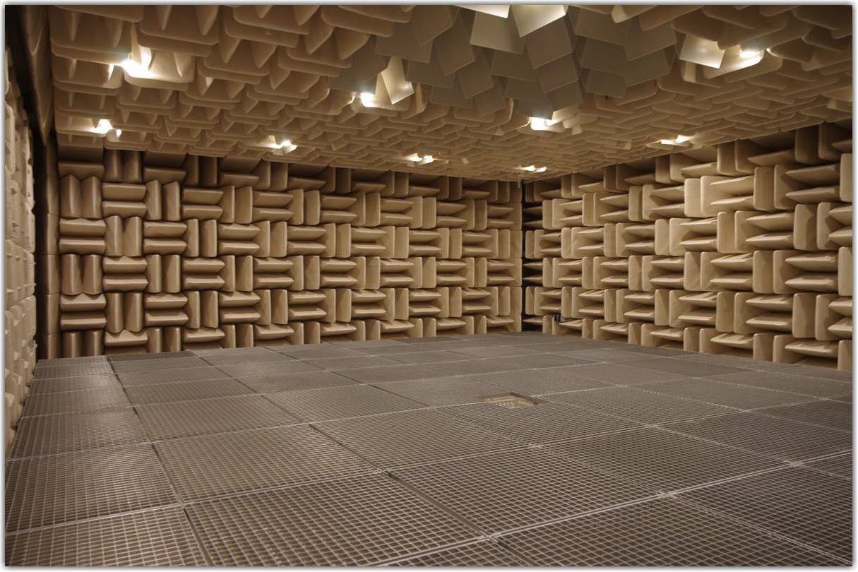
Free field is very hard to come by. However, you can create a free field applicable for calibration in anechoic chambers or in the open air, away from reflecting surfaces. You can see an example of such chamber in the image below.
When we talk about the characteristics of the microphones by pressure, we assume that the amplitude and the phase of the sound wave are the same at every given point of the field. Such fields appear in acoustic calibrators, where the size of cavity is small compared to the wavelength.
The equipment for measurement in free field is rare, which is why TestUp only supports calibration based on pressure, in particular:
- Calculating sensitivity on the base frequency (pressure field);
- Finding the frequency response of the microphone (pressure field);
Let us discuss these two calculation methods in more detail.
Calibration Equipment Set
The following items are usually included in the calibration set:
- reference microphone
- electrostatic actuator
- acoustic calibrator
- vibration controller with highly accurate ADC and DAC (24 bits with RULA controllers)
- PC with calibration software.
The system can also include an acoustic coupler.
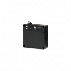
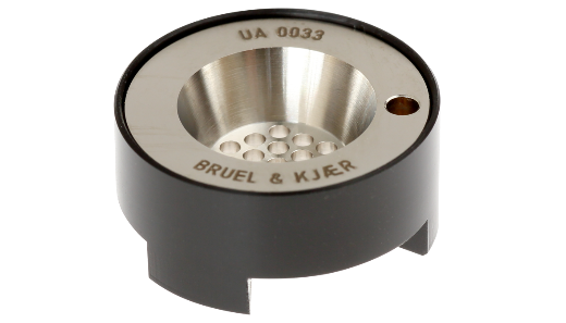
An acoustic calibrator is a device that sends a sound pressure signal of a known level and frequency to the microphone.
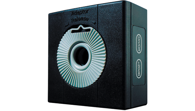
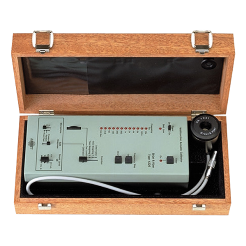
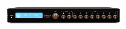
In the picture 1 above you can see 4231 Bruel & Kjaer acoustic calibrator. It can hold 2 levels of sound pressure — 94 and 114 dB — on the frequency of 1000 Hz. Some expensive calibrator models, e.g. 4226 by Bruel & Kjaer on the picture 2, support a fixed number of frequencies, for instance, an octave row.
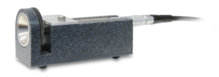
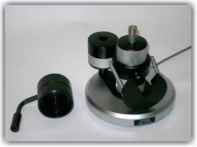
An electrostatic actuator is a device that imitates the impact of sound pressure through a direct impact of the electric field on the microphone membrane. The above picture is a photograph of a RULA-designed actuator; picture 2 is an actuator designed by Bruel & Kjaer.
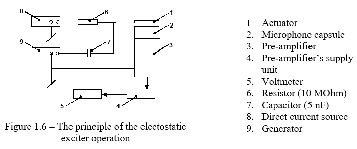
A sum of direct and alternating voltage is delivered to the plate of the exciter. The membrane of the microphone starts vibrating under the influence of the electric field. The detailed information about the electrostatic actuators can be found in IEC 61094-6:2004 Electrostatic actuators for determination of frequency response. The photo below shows a Bruel & Kjaer acoustic coupler.
A coupler is used to obtain the sensitivity of a microphone by comparison. The reference microphone and the calibrated one are subject to the same sound pressure impact. In this case, the ratio of the sensitivities is equal to the ratio of the voltages at the outputs of these microphones. The sensitivity of the calibrated microphone Mcal is found through the sensitivity of the reference microphone and the ratio of the voltages Ucal / Uref using the formula: 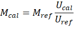
The coupler creates a closed chamber, and a high-quality electrostatic exciter is connected to it in the upper part. The membranes of the microphones inside the coupler form a part of the inner walls of the chamber.
In order for the sound impact to be the same on the reference and calibrated microphones, the greatest size of the chamber L must be much smaller than the length of the wave λ in the air. This limits the maximum operating range of the coupler to 5 kHz.
An acoustic coupler is a very cost-effective solution because it substitutes for an expensive multi-frequency calibrator.
Microphone calibration procedure
Let's talk about how to calibrate microphones in RULA software in more detail.
To measure the microphone sensitivity on the base frequency, assemble the scheme shown below.
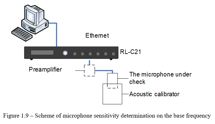
The sensitivity of the microphone is calculated by the formula:

where
- M – microphone sensitivity;
- P – calibrator’s sound pressure, Pa;
- Umuc – voltage measured at the output of the calibrated microphone.
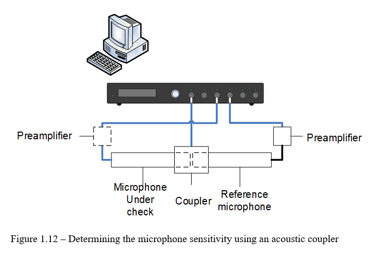
In most cases, the level of sound pressure in the calibrator is measured directly before microphone calibration. To do it, the scheme shown below is assembled.
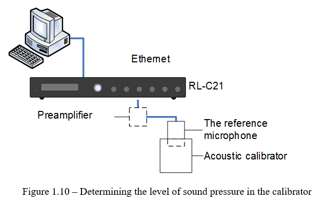
Sound pressure is calculated using the formula:

where
- Мref – sensitivity of a reference microphone;
- P – sound pressure of the calibrator, Pa;
- Uref – voltage measured at the output of the reference microphone.
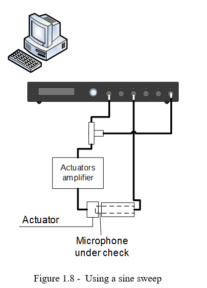
After that, an electrostatic actuator is included in the scheme in order to measure FRF.
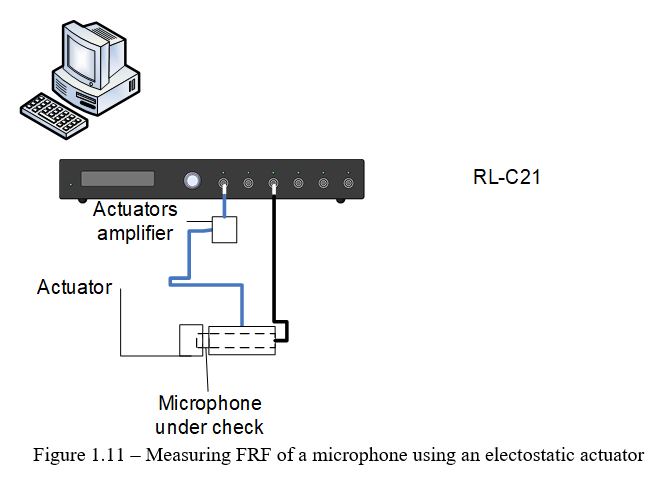
When measuring a microphone’s FRF, the required level of voltage is set on the base frequency first, so that the signal from the microphone would considerably exceed noise.
This voltage is then reproduced on all frequencies of the third-octave row in the microphone’s frequency range.
For each of the frequencies, the shift of the sensitivity from the sensitivity on the base frequency is calculated using the formula:
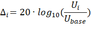
where
- ∆i – sensitivity shift on the i-frequency, dB;
- ∆i – microphone output voltage measured on the i-frequency;
- Ubase – microphone output voltage measured on the base frequency.
The method of measuring sensitivity on each frequency in turn has two disadvantages:
- The measurement takes a considerable time, even in the automated mode;
- As the procedure takes much time, the probability of noises (someone sneezed, a door opened) increases.
RULA Technologies engineers have come up with an algorithm, where the microphone is subject to a signal, which would contain all frequencies of the given range. In this case, a short sine sweep (2 to 8 seconds) in the range from 20 Hz to 20 000 Hz is delivered to the actuator, and, through it, to the microphone.
After that, the spectra of input and output signals are analyzed and FRF of the microphone is determined.
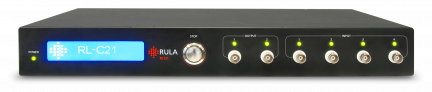
The output signal from RL-C21 can be closed to one of the inputs.
In case there is no actuator or it does not maintain the necessary base frequency, you can use an acoustic coupler to determine the sensitivity on the base frequency.
In this case, the sensitivity of the microphone is calculated uisng the formula:

Steps of Calibration Procedure
Measurement Settings
Similar to working with accelerometers, the first step is to specify the serial number and the date of the latest calibration.
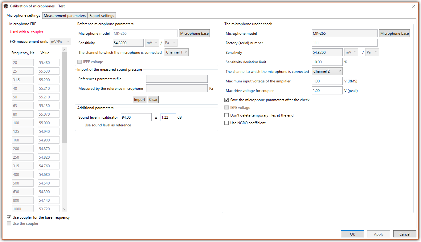
Next, enter the parameters of calibrated and reference microphones and measurement settings in the window below.
Specify the parameters of the reference microphone using the reference microphones database, as shown below.
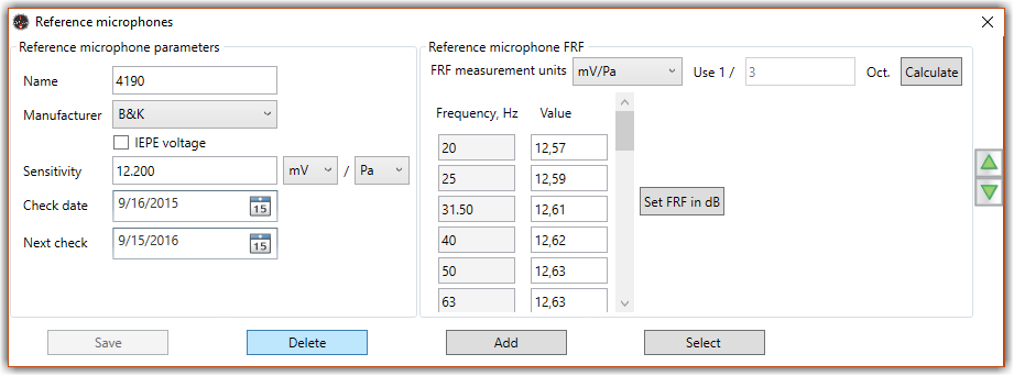
Choose the microphone manufacturer from the “Manufacturer” drop-down list. If you’ve set the IEPE supply flag, it means that the microphone has IEPE supply, so the system will take it for an IEPE sensor. Specify the sensitivity of the microphone on the base frequency in the Sensitivity field.
The Reference microphone FRF panel allows you to set the dependence of the microphone sensitivity from frequency. In this table, fill the FRF (pressure field).
Select the following parameters of the calibrated microphone from the database:
- Manufacturer
- Model
- Sensitivity
- If the microphone has IEPE supply
- Base frequency in Hz
- Start and end operating frequencies of the microphone
- Sensitivity shift limit
You should also specify the following measurement settings:
- If an acoustic coupler will be used for determining sensitivity
- Level of sound pressure in the calibrator or coupler
- Channels to which the calibrated and reference microphones are connected
- if the signal of “sine sweep” type is used when determining FRF.
Running Measurements
As sensitivity and FRF measurements are performed using different devices, the following two steps are realized in TestUp:
- Measuring sensitivity on the base frequency;
- Microphone FRF determination.
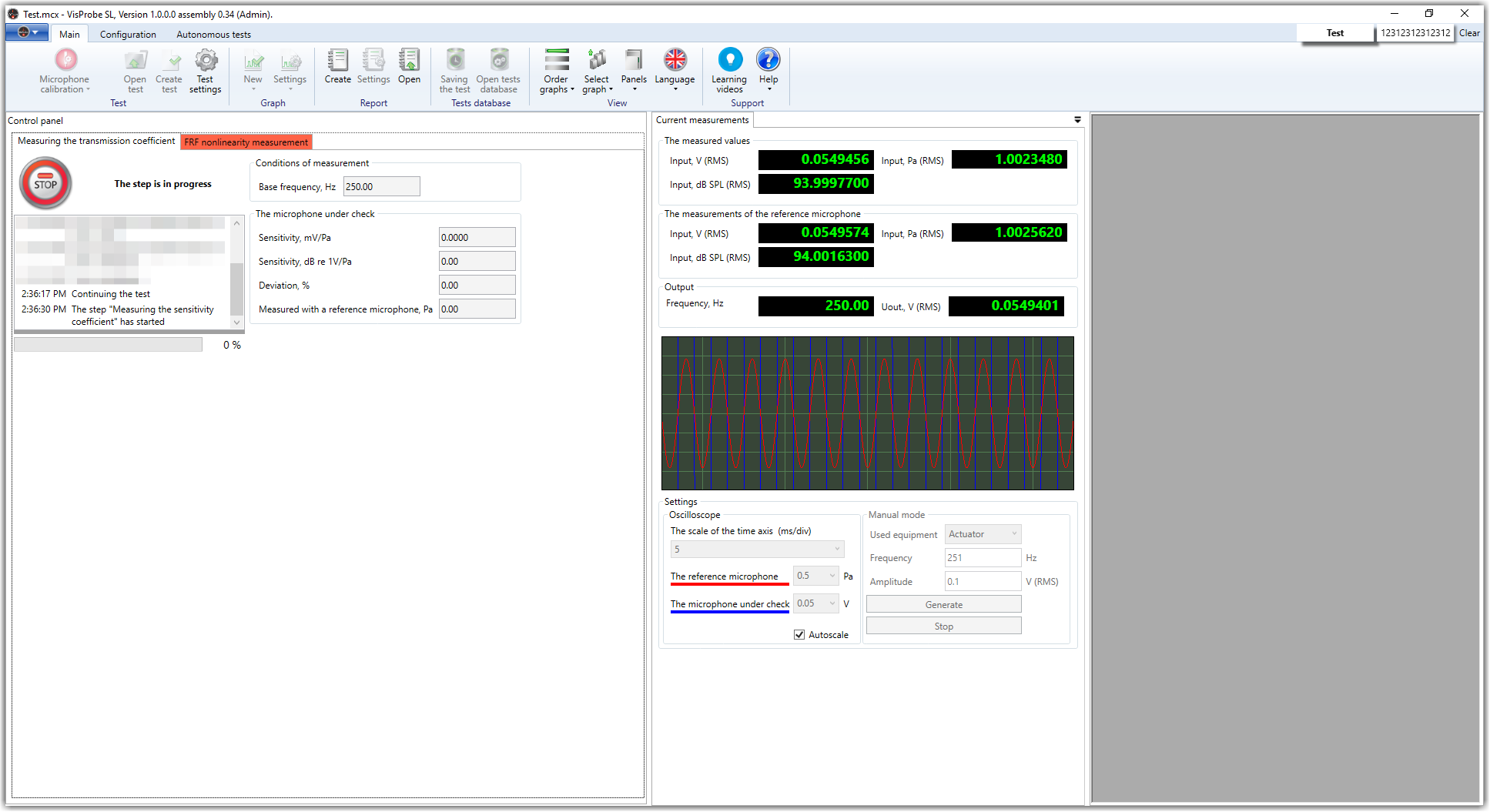
Similarly to accelerometer calibration, the program gives detailed tips when running the measurements.
If you have any questions regarding microphone calibration, contact our 24/7 technical support per email or call +371 6610 2166.