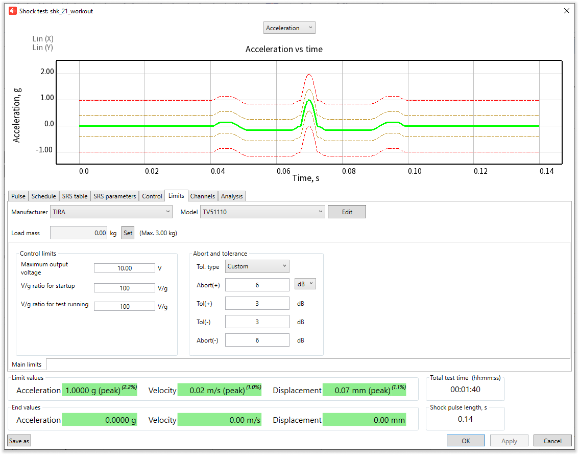
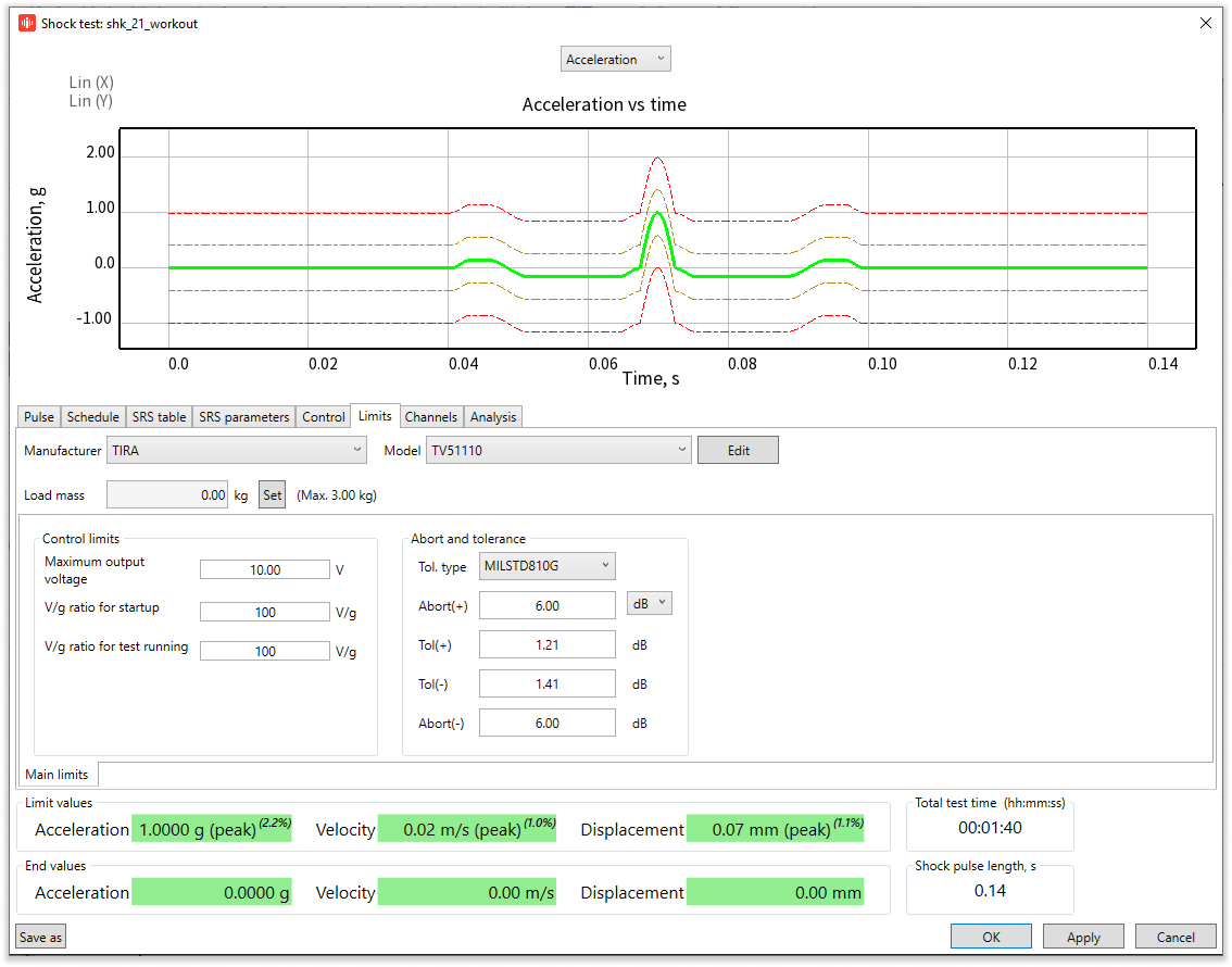
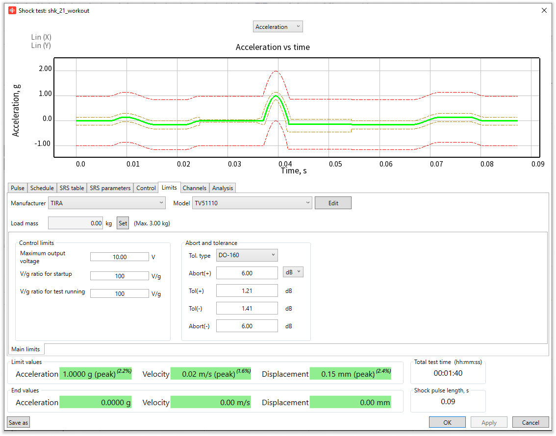
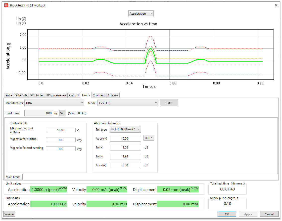
To set the shock limits in the TestUp software for vibration testing, use the Limits tab in the Test Settings panel. There are three main groups of options here:
- Shaker limits;
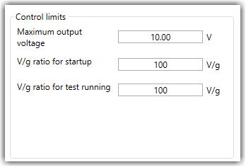
- Control limits;
- Abort and Tolerance limits.
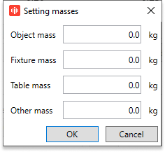
Input the mass of the test object in the Load mass field. To the right of this field, you can see the maximum possible object mass for the selected shaker, considering the set profile and schedule. To set Load mass, click Set, and in the Setting masses window set: load mass, fixture mass, table mass, and any other mass attached to the object or table fixture.
Click Edit to enter the Shaker settings window. Here you can set the limit values for Acceleration, Velocity, Displacement, Fore, and Maximum driving voltage specified by the shaker manufacturer.
The Shaker limits category includes three elements: shaker manufacturer, shaker model, and object mass. The drop-down lists of Manufacturer and Model allow you to specify the shaker used for tests. All added shaker models will be shown in the Model drop-down list when you choose a manufacturer.
The Maximum driving voltage is the maximum voltage value delivered to the output channel. With this parameter, you can forcefully limit the output channel voltage, based on the maximum possible input voltage value of the power amplifier.
The settings of the selected shaker must correspond to the vibration shaker in use. If the settings do not correspond to the assembled shaker, the drive voltage values delivered to the shaker may be too great. Equipment damage, in this case, will not be covered by warranty.
Going back to the Limits window, V/g ratio for startup and V/g ratio for test running allow setting the maximum acceptable value of this ratio at startup and during the test. In this case, V stands for drive shock pulse power in  , and g – stands for response shock pulse power in
  . These parameters allow you to quickly detect the sensors that are connected or installed incorrectly.
For example, the “V/g ratio for test running” parameter is set as  , and the shock with the power of
  is delivered to the output. The disconnection of the sensor connected to the RULA controller’s control input occurs. If during the shock its power falls below
  , the test will be aborted following an emergency stop.
The Abort and tolerance group of the Limits tab allows you to specify the abort and tolerance levels. The levels are specified relative to task shock pulse power, the parameters of which are entered in the Pulse tab. For control, the function is the square root of the shock pulse. This parameter is called Shock pulse power in TestUp. It is calculated according to the formula  , where:
- N – shock pulse power;
- Tb and Te – the time of start and end of the main shock pulse;
- A(t) – the dependence of shock acceleration from time.
If the response shock pulse power gets bigger or smaller than the tolerance level, the message of going below or above the tolerance level will appear in the test log.
If the response shock pulse power gets bigger or smaller than the abort level, the message of the emergency stop will appear in the test log and the test will be stopped if the stop is allowed for that reason.
The shock pulse power and tolerance or abort values are compared by absolute values.
The Abort and tolerance group has a drop-down list where you can select various types of limitations:
1. User-defined – the abort and tolerance levels of the Shock pulse power deviation from the task, taking into account the level specified in the schedule. The values in the Abort (-) and Abort (+) fields must be greater than or equal to the values in the Tol (-) and Tol (+) fields correspondingly. By default, the tolerance level is set at 3 dB, and abort levels – at 6 dB.
2. MILSTD 810G/H – the levels of shock pulse power deviation in reference to the task level are specified as per the international standard MILSTD 810G/H (US Ministry of Defense standard). The abort levels are user-defined.
3. DO-160 – the tolerance levels of the Shock pulse power deviation from the task, taking into account the level specified in the schedule are specified according to the international standard DO-160. The abort levels are user-defined.
4. BS EN 60068-2-27 – the tolerance levels of the Shock pulse power deviation from the task, taking into account the level specified in the schedule, are specified according to the international standard BS EN 60068-2-27 (BSI. British Standards. Environmental testing. Tests. Test Ea. and guidance. Shock. 2009). The abort levels are user-defined.
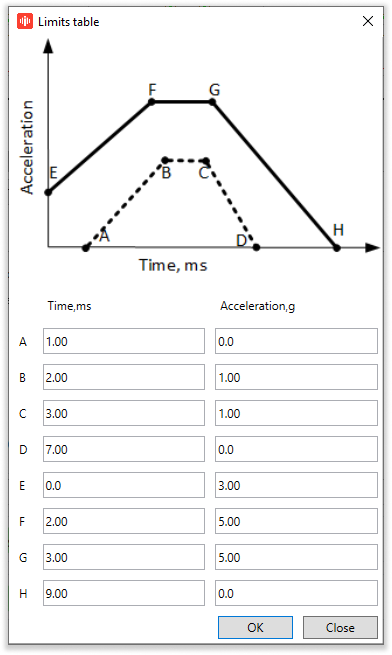
5. Table – the tolerance levels of the Shock pulse power deviation from the task, considering the level specified in the schedule, are specified according to the table entered by the user. The abort levels are user-defined.
The Table option specifies the graph of exceeded acceleration vs. time and the graph of lower acceleration vs. time with four points. If you want to enter the data of acceleration and time into the Limits table you need to press the [...] button to the right of the Table option in the drop-down list.
In conclusion, setting the additional shock limits is a convenient feature that provides an added degree of flexibility for Shock testing. This is also an effective instrument to keep your shaker safe during vibration testing.
If you have any questions regarding the Shock Limits or need help with choosing the right equipment for your task, drop us an email at contact@rula-tech.com or call +371 6610 2166.


