


Pierakstīties
Aizpildiet laukus un nosūtiet reģistrācijas pieteikumu. Jūsu pieteikums tiks pārskatīts pēc iespējas ātrāk.
Ja jums jau ir konts, lūdzu, pierakstieties vai atjaunojiet savu paroli.
Pierakstieties
Lai pieteiktos, aizpildiet laukus zemāk.
Un ir laba diena.
Ja jums nav konta, lūdzu, pierakstieties vai atjaunojiet savu paroli
Atjaunot paroli
Lai atiestatītu paroli, aizpildiet zemāk redzamo lauku. Pēc tam jums tiks paziņots e-pastā.
Ja jums nav konta, lūdzu, dziediet vai pierakstieties, ja tāds ir.
Risinājums.
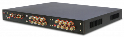
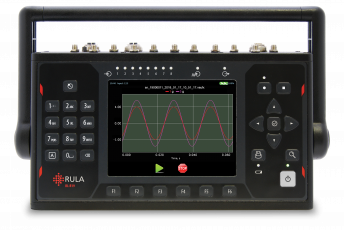
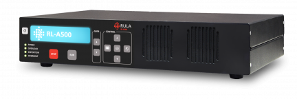
For this case, we offered RL-R19 to be used as a DAQ-system.
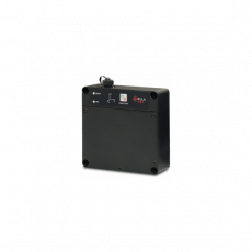
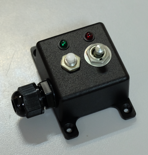
Remote control
To simplify the procedure for the crew, we used a remote control to run RL-R19. It has the necessary minimum of control tools and LED indicators.
Start of balancing
The first step was the initial run. The helicopter performed a standard flight procedure in several modes.
The following flight modes were selected as the relevant ones
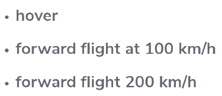
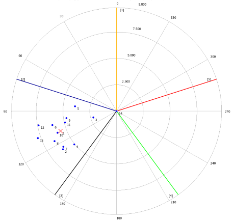
Hover
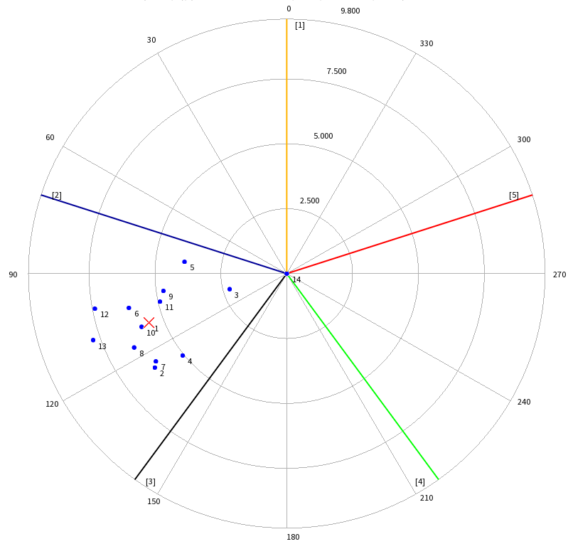
In this diagram you see the position of 5 blades and a number of points, which show the unbalance vector at a particular time.
The red cross shows the averaged value of unbalance.
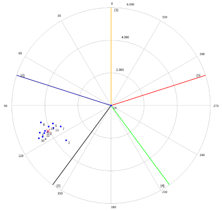
Forward flight 100 km/h
The positioning of points close together means that the increased level of vibration is due to the main rotor unbalance. The distance of points from the center and the space occupied by the cloud of points tells us that the balancing procedure has good chances of being a success.
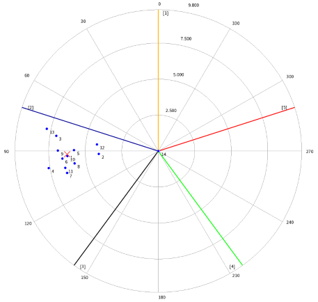
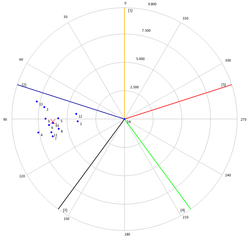
Forward flight 200 km/h
Even though the unbalance vector has slightly changed, the cloud of points is still dense and located in about the same segment of the diagram. It shows that the nature of the unbalance is fixed, e.g. it is due to the uneven mass distribution in the rotor and does not depend on the flight mode.
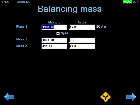
Balancing
To determine the “heavy point”, the trial weight of 500 g was placed on the first blade of the main rotor.
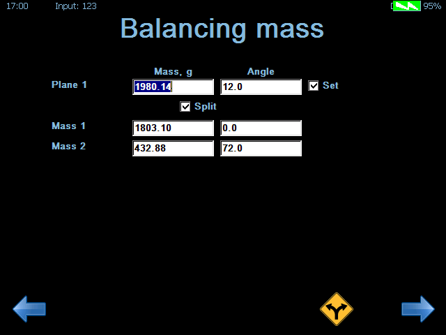
After that, the unbalance vector shifted very little in phase, which signifies that the corrective weight is to be placed around the angle of the first blade. It was calculated that the mass of the corrective weight is 1980.14 g and the angle of its placement is 12⁰.
The corrective weight was split onto two nearby blades:
- 1803.1 g on the first blade (the actual weight mounted - 1800 g)
- 432.88 g on the second blade (the actual weight mounted - 400 g)
First, a initial run was performed.
The following flight modes were selected as the relevant ones:
- Hover
- Forward flight at 100 km/h

- Forward flight at 200 km/h
The analysis of the acquired data in VisAnalyser showed that the main rotor has some imbalance. The imbalance vector retained practically the same phase in different flight modes.
To determine the “heavy point”, the trial weight of 500 g was placed on the first blade of the main rotor. After that, the imbalance vector shifted very little in phase, which signifies that the corrective weight is to be placed around the angle of the first blade. It was calculated that the mass of the corrective weight is 1980.14 g and the angle of its placement is 12⁰.
The corrective weight was split into two nearby blades:
- 1803.1 g on the first blade (the actual weight mounted - 1800 g)
- 432.88 g on the second blade (the actual weight mounted - 400 g)
Hover: vibration was decreased from 5.56 mm/s to 2.15 mm/s.
100 km/h: vibration was decreased from 4.11 mm/s to 1.25 mm/s.
200 km/h: vibration was decreased from 6.24 mm/s to 3.49 mm/s.


Submit your request
Vai jums ir jautājumi vai ieteikumi par mūsu produktiem? Aizpildiet veidlapu, un jūs esat viens solis tuvāk atbildei.


Polityka Prywatności
Welcome to our Privacy Policy
Your privacy is critically important to us.
RULA Technologies is located at:
Balta iela 7, Riga, LV-1055, Latvia
It is RULA Technologies's policy to respect your privacy regarding any information we may collect while operating our website. This Privacy Policy applies to https://rula-tech.com (hereinafter, "us", "we", or "https://rula-tech.com"). We respect your privacy and are committed to protecting personally identifiable information you may provide us through the Website. We have adopted this privacy policy ("Privacy Policy") to explain what information may be collected on our Website, how we use this information, and under what circumstances we may disclose the information to third parties. This Privacy Policy applies only to information we collect through the Website and does not apply to our collection of information from other sources.
Depending on your activities when visiting our Website, you may be required to agree to additional terms and conditions.
- Website Visitors
Like most website operators, RULA Technologies collects non-personally-identifying information of the sort that web browsers and servers typically make available, such as the browser type, language preference, referring site, and the date and time of each visitor request. RULA Technologies's purpose in collecting non-personally identifying information is to better understand how RULA Technologies's visitors use its website. From time to time, RULA Technologies may release non-personally-identifying information in the aggregate, e.g., by publishing a report on trends in the usage of its website.
RULA Technologies also collects potentially personally-identifying information like Internet Protocol (IP) addresses for logged in users and for users leaving comments on https://rula-tech.com. RULA Technologies only discloses logged in user and commenter IP addresses under the same circumstances that it uses and discloses personally-identifying information as described below.
- Gathering of Personally-Identifying Information
Certain visitors to RULA Technologies's websites choose to interact with RULA Technologies in ways that require RULA Technologies to gather personally-identifying information. The amount and type of information that RULA Technologies gathers depends on the nature of the interaction. For example, we ask visitors who sign up at https://rula-tech.com to provide a username and email address
- Security
The security of your Personal Information is important to us, but remember that no method of transmission over the Internet, or method of electronic storage is 100% secure. While we strive to use commercially acceptable means to protect your Personal Information, we cannot guarantee its absolute security.
- Links To External Sites
Our Service may contain links to external sites that are not operated by us. If you click on a third party link, you will be directed to that third party's site. We strongly advise you to review the Privacy Policy and terms and conditions of every site you visit.
We have no control over, and assume no responsibility for the content, privacy policies or practices of any third party sites, products or services.
- Protection of Certain Personally-Identifying Information
RULA Technologies discloses potentially personally-identifying and personally-identifying information only to those of its employees, contractors and affiliated organizations that (i) need to know that information in order to process it on RULA Technologies's behalf or to provide services available at RULA Technologies's website, and (ii) that have agreed not to disclose it to others. Some of those employees, contractors and affiliated organizations may be located outside of your home country; by using RULA Technologies's website, you consent to the transfer of such information to them. RULA Technologies will not rent or sell potentially personally-identifying and personally-identifying information to anyone. Other than to its employees, contractors and affiliated organizations, as described above, RULA Technologies discloses potentially personally-identifying and personally-identifying information only in response to a subpoena, court order or other governmental request, or when RULA Technologies believes in good faith that disclosure is reasonably necessary to protect the property or rights of RULA Technologies, third parties or the public at large.
If you are a registered user of https://rula-tech.com and have supplied your email address, RULA Technologies may occasionally send you an email to tell you about new features, solicit your feedback, or just keep you up to date with what's going on with RULA Technologies and our products. We primarily use our News page to communicate this type of information, so we expect to keep this type of email to a minimum. If you send us a request (for example via a support email or via one of our feedback mechanisms), we reserve the right to publish it in order to help us clarify or respond to your request or to help us support other users. RULA Technologies takes all measures reasonably necessary to protect against the unauthorized access, use, alteration or destruction of potentially personally-identifying and personally-identifying information.
- Aggregated Statistics
RULA Technologies may collect statistics about the behavior of visitors to its website. RULA Technologies may display this information publicly or provide it to others. However, RULA Technologies does not disclose your personally-identifying information.
- Cookies
To enrich and perfect your online experience, RULA Technologies uses "Cookies", similar technologies and services provided by others to display personalized content, appropriate advertising and store your preferences on your computer.
A cookie is a string of information that a website stores on a visitor's computer, and that the visitor's browser provides to the website each time the visitor returns. RULA Technologies uses cookies to help RULA Technologies identify and track visitors, their usage of https://rula-tech.com, and their website access preferences. RULA Technologies visitors who do not wish to have cookies placed on their computers should set their browsers to refuse cookies before using RULA Technologies's websites, with the drawback that certain features of RULA Technologies's websites may not function properly without the aid of cookies.
By continuing to navigate our website without changing your cookie settings, you hereby acknowledge and agree to RULA Technologies's use of cookies.
Privacy Policy Changes
Although most changes are likely to be minor, RULA Technologies may change its Privacy Policy from time to time, and in RULA Technologies's sole discretion. RULA Technologies encourages visitors to frequently check this page for any changes to its Privacy Policy. Your continued use of this site after any change in this Privacy Policy will constitute your acceptance of such change.
- Processing Policy
- Credit & Contact Information
This privacy policy was created at https://termsandconditionstemplate.com/privacy-policy-generator/.
If you have any questions about this Privacy Policy, please contact us via email or phone.